7A1. General. The ventilation arrangement consists of four systems: 1) the engine
induction, 2) the ship's supply, 3) the ship's exhaust, and 4) the battery exhaust. The ship's
supply and ship's exhaust systems are cross-connected as are also the ship's exhaust and battery
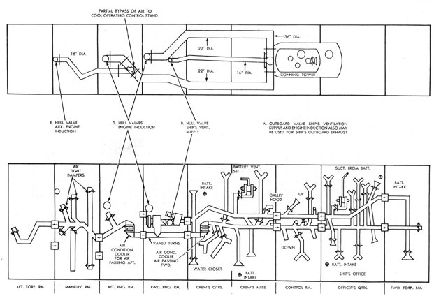
system. (See FigureA-10.)
7A2. Engine induction. Air to the engine is supplied by natural induction through a
36-inch diameter ventilation stack and outboard valve in a compartment in the after end of the
conning tower fairwater. The bottom of this stack has three branches, one 16-inch diameter
branch for ship's supply and two 22-inch diameter branches, one port and one starboard. All the
branches are located in the superstructure. The port pipe runs aft to a hull valve in the top of the
inner shell, near the middle of the forward machinery compartment. The starboard pipe runs aft
to a hull valve in the top of the inner shell near the middle of the after machinery compartment.
These hull valves permit passage of air directly to their respective machinery compartments. Just
forward of the after hull valve a 22 x 22 x 16-inch lateral bypass damper fitting is inserted in the
induction pipe, the 16-inch outlet of which discharges into a 16-inch pipe, running aft to an
auxiliary hull valve in the top of the inner shell in the maneuvering room, aft of the maneuvering
control stand. This air, when thus bypassed, is for the purpose of creating lower temperatures in
the vicinity of the control stand and eventually circulates forward again for consumption by the
engines in the machinery compartments through the door or exhaust bulkhead valves in the
forward maneuvering room bulkhead.
7A3. Ship's supply. During normal surface operation, ship's air is supplied through
the
combination engine induction and ship's supply outboard valve (Figure 7-1) located in the
after end of the conning tower fairwater. A 16-inch diameter pipe in the superstructure runs from
this stack to a hull valve in the top of the inner shell near the forward end of the forward
machinery compartment. The 4000 cubic feet per minute ship's supply blower, which receives its
air through this hull valve, attached fitting and inlet pipe, is just aft of the former and discharges
into a splitter fitting directing air into both forward and after supply mains. This splitter fitting has
a fixed damper that has been adjusted to divide the flow forward and aft in the right proportions.
The supply mains run to the forward and after compartments of the vessel and are equipped with
valves, branches, and louvers for adequate air distribution to all necessary spaces.
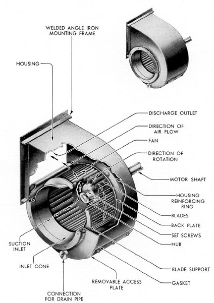
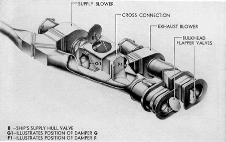
7A4. Ventilation blowers. Ventilation blowers are employed to move air within the
hull supply, hull exhaust, and battery exhaust systems. Each of the blowers is driven by an
individual direct-drive electric motor.
Figure 7-2 is an illustration of a typical ventilation blower of the type used on the submarine.
The hull supply blower has a capacity of 4000 cubic feet per minute. It is powered by an
electric motor rated at 2 to 5 horsepower.
The hull exhaust blower has a capacity of 2560 cubic fee per minute at 1750 rpm. Its motor
is rated at 2 to 4 horsepower.
Each of the two battery exhaust systems has two blowers. These blowers are rated at 500
cubic feet per minute at 2780 rpm. Power is supplied to each blower by a 1 1/4-horsepower electric
motor. A damper, placed between the inlet ports of the two
76
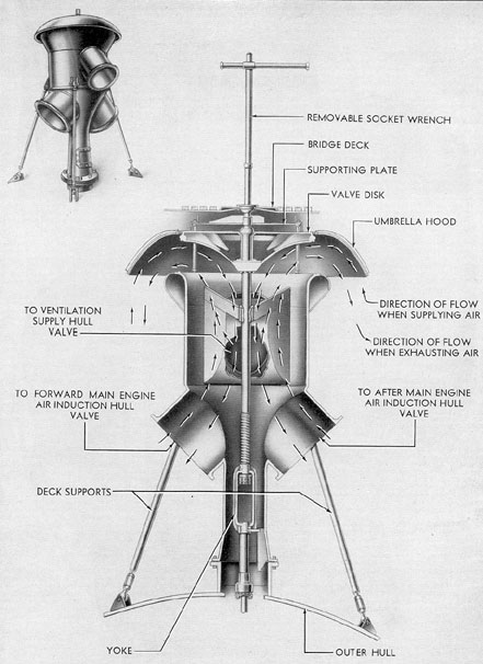
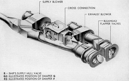
Figure 7-1. Engine induction and ship's supply outboard valve.
77
blowers of each battery exhaust system, permits the use of one or both blowers.
7A5. Ship's exhaust. The 2500-cubic feet per minute ship's exhaust blower is in the
forward end of the forward machinery compartment and receives its air from a main, running
forward to the after end of the forward torpedo room, having adequate valves, branches, and
louvers from all necessary spaces forward of the forward machinery compartments. During
normal surface operation, the discharge from the exhaust blower is directed into the forward
machinery compartment through a damper-controlled louver in a fitting adjacent to the blower.
When the ship is at the dock or laying to, with engines not running, this air, plus that discharged
into all compartments aft of the crew's quarters by the ship's supply system, may find its way
overboard via open hatches or engine induction hull valves, whichever may be most desirable
under existing weather conditions. Any doors or exhaust bulkhead valves in the after bulkheads,
necessary to permit natural egress of exhaust air from the boat by the above-mentioned means,
should be left open. When the submarine is cruising on the surface, the discharge from the
exhaust blowers is consumed by the engines. In this condition all airtight dampers in supply
branches should be shut in both machinery compartments and maneuvering room. If air is being
supplied to the after torpedo room, exhaust bulkhead valves must be left open in both forward
and after maneuvering room bulkheads so that exhaust air may get back to machinery
compartments for consumption by the engines.
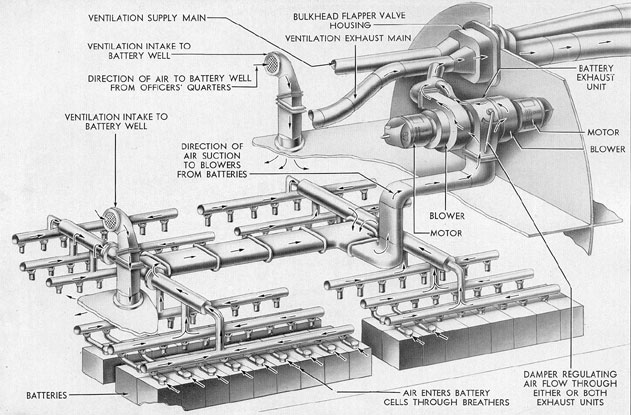
7A6. Battery exhaust. Each of the two battery tanks normally receives its supply
from the compartment above via two battery intakes, one near each end of the room. In an
emergency, these may be closed off by gas-tight covers stowed near the intakes. In each battery
tank, air is sucked through each cell by a network of hard rubber piping, eventually consolidating
into one pipe connecting
to a single fitting in the platform deck above the batteries. (See Figure 7-3.) To the top of this
fitting is attached a riser, leading up to a damper fitting connected to the inlets of two battery
exhaust blowers. Either or both blowers may be operated at any one time for each battery. The
forward set is located in the overhead of the chief petty officers' quarters and the after set is
overhead of the crew's mess room. Each pair of blowers discharges into its own common fitting,
having a partial damper for flow regulation. These fittings discharge into the ship's exhaust main
near the battery blowers.
During periods of battery exhaust, gases have high hydrogen content (see Section 7A7), a
damper, normally left entirely or partly open to the inlet of the ship's supply blower, may be fully
closed, thereby diverting all exhaust air (which contains battery gases) overboard through the
normal ship's supply outboard piping system. In such a position, the damper uncovers a screened
opening permitting inboard supply to the ship's supply blower from the forward machinery
compartment.
An orifice plate is inserted in the battery exhaust riser from each battery compartment, and
pressure fittings from each side of each orifice plate are piped to separate air flow meters in the
maneuvering room. The type of meter used is an arrangement of differential pressure gage known
as the Hays Air Flow Meter. An indication of the quantity of air flow indicators. Each of
these indicators is provided by a scale marked in cubic feet per minute.
The operation of the battery ventilation system covering fan speeds, controller settings, and
meter readings is detailed in the Bureau of Ships Manual, Chapters 88 and 62.
All piping and fittings in the superstructure are designed to resist sea pressure at the maximum
depth of submergence.
Three conditions under which it may be necessary or desirable to recirculate the air inside the
ship rather than take in air from the outside as described for normal
78
Figure 7-2. Ventilation blower.
79
Figure 7-3. Battery ventilation.
80
operation are: a) when submerged, b) when using the air-conditioning coolers, and c) in case of damage to
the outboard piping. When recirculation is taking place, all hull ventilation valves are shut. The
ship's exhaust blower is discharging into the inlet of the ship's supply blower and the exhaust air
from the after compartments of the ship is being picked up by the ship's supply blower. All this is
accomplished by means of two damper-controlled louvers in a series of pipes and fittings between
the discharge of the ship's exhaust and the inlet of the ship's supply blowers. To permit passage
of exhaust air back to the forward machinery compartment, all bulkheads between the forward
end of the after torpedo room and the machinery compartments must be open to the
compartments surrounding them by means of open exhaust bulkhead valves or doors.
Two air-conditioning coolers for cooling and drying the air are installed in the supply lines;
the larger forward one is located in the after end of the crew's quarters and the smaller after one is
located in the forward end of the after machinery compartment. When the humidity in the vessel
becomes excessive, the quantity of air passing through the cooler should be reduced in order that
the temperature of the air that passes through the cooler may be lowered below the dewpoint and
thereby increase the quantity of water extracted from the air. The coolers are provided with
drains to collecting tanks or engine room bilges.
The supply and exhaust mains at the watertight bulkheads are attached to pressure-proof
hoods surrounding lever-operated bulkhead valves on each side of the bulkhead. Each pair of
valves is operated by the lever on either side of the bulkhead. No ship's exhaust main exists aft of
the ship's exhaust blower, but provisions for allowing exhaust air in the after end of the ship to
get back to the machinery compartments have been made. Each of the two watertight bulkheads
at the two ends of the maneuvering room has a pair of light hoods surrounding lever-operated
bulkhead valves on each side of the
bulkhead. Each pair of valves is operated by the lever on either side of the bulkhead. Exhaust air may
travel forward from the after to the forward machinery compartments only by means of the
watertight door which must be left open for this purpose.
The ship's ventilation supply and engine induction valve, located in the after end of the
conning tower fairwater, is operated hydraulically or by hand and is locked in either the open or
shut positions by hand operation. The hand gear consists of a hand crank with two handles which
operate a worm and worm gear so arranged as to raise and lower the valve stem through the hull
by a bell crank and slotted lever arrangement. A double-acting piston type of hydraulic gear is in
the power position. The hand gear also moves the hydraulic piston and can be used only when the
control lever for engine induction on the flood control manifold is in the neutral position.
External gagging on the engine induction and ship's supply outboard valve is accomplished by
a wrench-operated valve stem set flush with the deck. The valve stem is supported by a yoke
superimposed on the valve body and is protected by a cover projecting slightly above the deck.
Gagging of the engine induction and ship's supply outboard valve gags or position locks all internal operating gear. The operating gear for the engine induction and ship's supply outboard valve is fitted with a contact maker
for the indicator lights in the control room, thus indicating the position (open or shut) of the
valve.
There are four hull valves: one ship's supply, two engine induction, and one maneuvering
room (auxiliary engine) induction. All four valves are of the flapper type and are gagged from the
inside of the ship. All hull valves seat with pressure in the external piping
The operating gear for each of the following hull valves, one ship's supply, two engine
induction, consists of an operating lever and
81
a quick releasing gear located at a suitable distance from the valve and connected to it by means
of intermediate levers and connecting rods. For opening each valve, the operating lever must be
used, and may be used for closing to ease the valve to its seat after tripping. However, the valve
can be shut in an emergency by squeezing the handles, thus tripping the quick-releasing
mechanism which permits the valve to seat by its own weight.
The operating gear for each hull valve is fitted with a contact maker for indicator lights in the
control room and engine rooms to show open and shut positions.
7A7. Hydrogen detecting systems. There are two types of hydrogen detectors in
service; one is manufactured by the Cities Service Company (type N.H.D.) And the other by the
Mine Safety Appliance Company (type M.S.A.). The function of the detectors is to take a sample
of exhaust air continuously from the batteries and indicate the percentage of hydrogen
concentration in the battery ventilation ducts.
The operation of both types of detectors is based on the principle of a balance Wheatstone
bridge circuit. The air sample is drawn, by means of a motor-driven pump, across one leg of the
balanced circuit where it is caused
to burn with an intensity dependent upon the amount of hydrogen present. The heat created heats
the leg and increases its resistance, thereby creating an electrical unbalance in the entire circuit.
The meter connected across the bridge circuit then shows a deflection on a properly divided scale
which is directly proportional to the percentage of hydrogen present in the air sample.
In addition to the meter indication, the M.S.A. type has a white light connected in the circuit,
indicating normal operation as long as the hydrogen content is below 3 percent. When the meter
pointer indicates 3 percent on the scale, the circuit to a red warning light is closed. This red
warning light will remain ON despite a decrease in hydrogen content until manually reset. Both
meter and light indications are transmitted to repeater instruments in the maneuvering room.
The type N.H.D. detector is supplied with 115- to 120-volt alternating current directly from
the a.c. bus of the I.C. switchboard. This system uses a rectifier to convert the alternating current
into direct current for the bridge circuit.
The M.S.A. type detector is supplied with 120-volt direct current from the lighting feeder.
B. AIR PURIFICATION
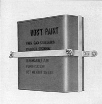
7B1. General description. Air purification is accomplished by the use of a CO2
absorbent as outlined in the Bureau of Ships instructions. Thirty-seven canisters, containing 15
pounds each of CO2 absorbent, are carried in stowages distributed in the several living
compartments.
The limiting percentage of CO2 is 3 percent. One percent or less is harmless, and after air
purification is started, efforts should be made to keep the percentage of carbon dioxide from
going above this amount. If, in any case, it becomes necessary to conserve the CO2 absorbent,
the percentages of carbon dioxide may be allowed to
increase during the last few hours of submergence, barely
reaching 3 percent at the time of surfacing.
Two percent of carbon dioxide will ordinarily not be noticed, but may show some discomfort
if work requiring strenuous exertion is attempted. Prolonged breathing of over 3 percent CO2
causes discomfort in breathing even at rest and becomes progressively dangerous above 4 percent.
The amount of carbon dioxide should never be allowed to exceed 3 percent. If, for any reason, it
does reach this concentration, it should be reduced as rapidly as possible. The limiting percent of
oxygen (O), on the other hand, should not fall below 17 percent.
To maintain the air of a submarine within these limits of purity, it is necessary to
82
reduce the increasing CO2 by chemical absorbents and to replenish the decreasing supply of
oxygen by bleeding certain amounts of oxygen or air into the submarine at regular intervals.
After the original enclosed air in the submarine has become so vitiated that the limiting values
of oxygen and carbon dioxide have been reached, one of the following procedures is necessary to
revitalize the atmosphere:
a) Bleed into the vessel 0.9 cubic foot of oxygen at atmospheric pressure per man per hour
and at the same time use the Navy standard carbon dioxide absorbent.
b) In lieu of oxygen, bleed into the vessel air from the compressed air tanks at the rate of 31
cubic feet of air at atmospheric pressure per man per hour. The introduction of additional air or
oxygen is solely to replenish the oxygen content in the compartment, which, under normal
submerged operating conditions, should not be allowed to fall below 17 percent. Irrespective of
whether compressed air or compressed oxygen is used for this purpose, the CO2 absorbent should
also be used, in view of the fact that exhaustive tests have indicated that the deleterious
physiological effects of high concentrations of CO2 are not alleviated appreciably by the
introduction of additional oxygen or air.
Figure 7-4. Carbon dioxide absorbent.
c) Start the high-pressure air compressors and pump a slight vacuum in the submarine,
charging this air into a low air bank; then release air into the submarine from a bank that was
charged on the surface.
Before submerging, whenever circumstances permit, thoroughly ventilate the vessel by closing
the hatches and ventilators in such a manner that all the air for the engines is drawn into the end
compartments and through the vessel. Under these conditions, run the engines for 5 minutes.
Since the contained air in the vessel at the outset of the dive is thus pure, it will not reach the
limiting values of 17 percent O and 3 percent CO2 until the expiration of a period of hours (X),
calculated by the following formula:
X = 0.04 C/N
where C = net air space of the submarine in cubic feet, and N = the number of men in the crew.
If submergence under ordinary operation conditions is less than 17 hours, oxygen or
compressed air replenishment and CO2 purification should not be necessary. However, if it is
predetermined that the time of submergence will be greater in any case than 17 hours, air
purification with the CO2 absorbent should be resorted to at the end of the periods indicated for
the respective class of ship.
CO2 absorbent is considerably more expensive than soda lime and great care should be
exercised in the handling and stowage of the containers. Exposure of them to external pressures,
such as are employed in testing compartments, would probably rupture their seams and destroy
their airtightness, thus causing eventual deterioration of the absorbent. The containers should be
removed during air testing of compartments.
This chemical absorbs CO2, by contact. The larger the area of the exposed surface of the
absorbent, the more efficient will be the result. When the length of submergence is such as to
necessitate CO2 elimination, the following steps should be taken:
a. Remove the mattress covers from the
83
mattresses of four lower bunks in the most convenient compartment provided with outboard
ventilation when surfaced.
b. Slit the mattress covers and spread the covers, single thickness, as smoothly and taut as
possible over bunk springs. Lash the edges to the bunk spring, if necessary, to keep it taut.
Remove the cover from one of the CO2 absorbent containers and pour about one-fourth of the
contents (approximately 3 1/2 pounds) on the cover. With a stick, spread the chemical as evenly as
possible over the mattress covers. In pouring the chemical from the container and in spreading it
on the mattress covers, care should be taken not to agitate it any more than necessary, as it is
caustic and the dust will cause throat irritation. The irritation, however, is only temporary and
while in many instances, coughing and sneezing may be induced, the effects are not harmful.
After working with the chemical, do not rub the eyes before the hands have been thoroughly
washed. If it should get into the eyes, painful, but not dangerous, irritation will result.
It may be relieved by washing the eyes with a solution of 1 part vinegar or lemon juice and 6
parts of water, or by careful washing with a quantity of fresh water. Do not spread the chemical
with the hands. Use a stick or other means. After spreading, stir it gently once each hour.
Under normal submerged operation conditions, the contents of one container when spread on
four mattress covers, as outline above, will absorb CO2 for 144 man hours, or will absorb the
CO2 produced by a crew of 33 men for approximately 4 1/2 hours; a crew of 43 men for
approximately 3 1/2 hours; a crew of 87 men approximately 1 3/4 hours.
When this chemical absorbs CO2, it evolves heat and is warm to the touch. The amount of
heat evolved depends upon the amount of CO2 present in the air and the rate of its absorption.
When the chemical no longer evolves heat in the presence of CO2, it has become saturated and
should be renewed. However, with small numbers of men in a compartment, the amount of CO2
generated will not be so great as that produced by a large number of men and the
amount of heat evolved will be slight. Consequently, when determining the warmth of the
chemical by touch, care should be taken that the material is fully spent before renewing it. If there
is any doubt on this point, leave the material spread on the mattress cover and spread an
additional charge on a split mattress cover in an additional bunk.
Because of the desirability of keeping the chemical from dusting as much as possible,
the refilling of the mattress cover and the spreading of the chemical should not be resorted to any
oftener than necessary. Accordingly, if submergence of any particular vessel is to exceed the time
of CO2 protection afforded by the chemical in the initial container, the contents of the necessary
additional container or containers should be spread out on additional mattress covers in the
amount necessary to furnish the increased man hours of protection required, in the same or other
convenient compartments, using approximately 3 1/2 pounds of the chemical on each additional
cover. The number of additional covers so used should depend upon the total number of men on
board and the estimated total time for which protection from CO2 must be afforded.
Higgins and Marriott carbon dioxide testing outfits are supplied for determining the
percentage of carbon dioxide in the air on submarines, and one of the outfits should be carried on
each submarine. The test with this apparatus is extremely simple and sufficiently accurate for all
practical purposes.
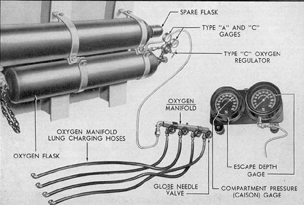
7B2. Oxygen system. Eleven oxygen standard containers are distributed throughout
the compartments of the vessel, the total capacity being sufficient to supply 37 cubic feet per man
of oxygen at normal temperature and atmospheric pressure. Two flasks are stowed in the forward
torpedo room and two in the after torpedo room. Each of the other compartments, including the
conning tower, has one flask. The flasks and regulator valves in the forward torpedo room, after
torpedo room, and the conning tower are piped to form banks in each of the three compartments
with a valve for the compartment and a manifold for escape arrangements.
84
Figure 7-5. Oxygen tank.
These manifolds, located in the forward escape trunk, conning tower, and just forward of the
escape trunk in the after torpedo room, have four valves. Each valve is provided with a 6-foot
length of rubber hose, fitting with a self-closing chuck of the Schrader type, for charging escape
lungs.
The containers in the other rooms are fitted with the regulator valves for replacing the oxygen
content of the air as desired.
The container or containers in one compartment are not connected with those in another
compartment.
C. VALVES
7C1. Classifications. The ventilation system is provided with valves classified as
follows:
All of these valves are described separately in the following sections.
7C2. Engine induction and ship's supply outboard valve. The engine induction and ship's
supply outboard valve is a 36-inch disc type valve (Figure 7-1), located in the air induction
standpipe in the superstructure abaft the conning tower. (See FigureA-10.)
When open, this valve permits air to enter the engine air induction and the hull ventilation
supply lines; when shut, it
85
Figure 7-6 Engine induction hull valve.
86
prevents the entrance of air or water to all
three lines. It is operated hydraulically from
the control room and is open only when the
vessel is on the surface. It can be operated
manually from the crew's mess.
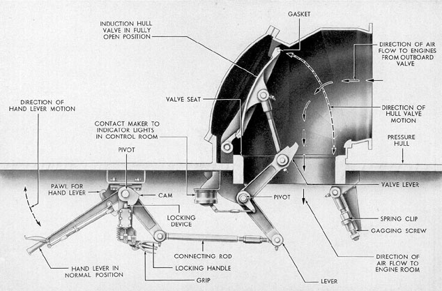
7C3. Engine induction hull valve. There are
two main engine induction hull valves located
beneath the superstructure at those points
where:
a. The port engine air induction line
goes through the pressure hull into the forward engine room.
b. The starboard engine air induction
line goes through the pressure hull into the
after engine room.
These valves are used to direct the flow
of air from the engine air induction and
ship's supply outboard valve to the forward
engine and after engine rooms. Each is manually operated from within the pressure hull.
Figure 7-6 shows the general construction of a typical engine induction hull valve.
Each valve is of the quick-closing type,
set into an angle housing. The outboard, or
inlet side of the housing connects to the
supply lines, bringing air from the engine
air induction and ship's supply outboard valve
in the superstructure. The inboard, of discharge side, leads into the pressure hull.
The valve is operated by a linkage extending to a hand lever. To open the valve,
the handle is moved downward until the cam
locking device is set. This will hold the valve
in the open position. With the cam locking
device set, the valve handle is returned to its
former position. The valve, however, is held
open by a quick-releasing cam locking device
on an open hair trigger for instant release
and quick closing when the locking handle
is depressed. This withdraws the locking
device, releases the cam, and allows the valve
to seat by its own weight. A link on the moving arm actuates a switch which, in turn,
operates a signal light in the control room,
indicating the position of the valve.
7C4. Maneuvering room induction hull valve.
The maneuvering room induction valve is
similar to but smaller than the engine induction hull valve shown in Figure 7-6. This
valve obtains its supply of air from a damper
fitting in the starboard engine induction line
located in the superstructure. The maneuvering room induction hull valve receives bypassed air to cool the operating control stand
in the maneuvering rooms. The amount of
air that is bypassed is controlled from the
after engine room by a lever-operated damper
in the damper fitting.
7C5. Ship's supply hull valve. The ship's
supply hull valve obtains its supply of air
from the engine induction and the ship's
supply outboard valve. The valve is similar
in construction to the engine induction hull
valve shown in Figure 7-6.
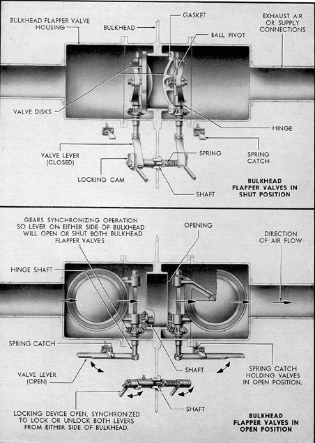
7C6. Bulkhead flapper valves. At each point
where the hull supply and hull exhaust lines
pass through a bulkhead, two bulkhead flapper
valves are installed. There is no exhaust line
aft of the forward engine room and therefore
no exhaust flapper valve between the forward
engine room and the after engine room bulkhead.
Figure 7-7 shows in schematic form the
general construction and arrangement of a
typical set of bulkhead flapper valves.
One valve is mounted on either side of
the bulkhead, with the pivot shaft projecting
downward and fitted with a handle. The two
pivot shafts are interconnected by gears so
that moving one shaft and valve will operate
the other simultaneously. This arrangement
permits operating the valves from either side
of the bulkhead.
A locking device, extending through the
bulkhead, permits locking or unlocking of
the operating handles from either side of the
bulkhead.
When shut, the bulkhead flapper valve
stops all ventilating air flow to the compartments forward or aft, as the case may be, of
the bulkhead on which the shut valve is
mounted.
Bulkhead flapper valves are also provided on all bulkheads aft of the forward
engine room except the bulkhead between the
forward and after engine room. These valves
permit free exhaust air to flow to the engine
rooms. All bulkhead flappers seat with compartment pressure.
87
Figure 7-7. Bulkhead flapper valves.
88
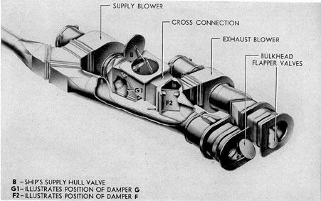
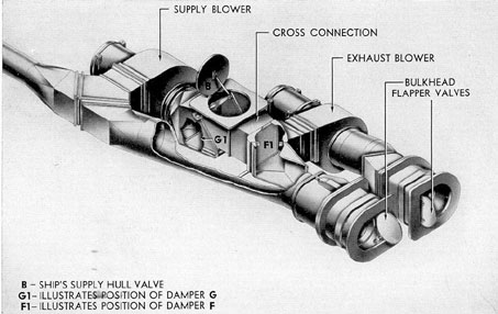
Figure 7-8. Ventilation operation condition No 1.
Figure 7-9. Ventilation operation condition No 2.
89
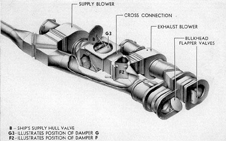
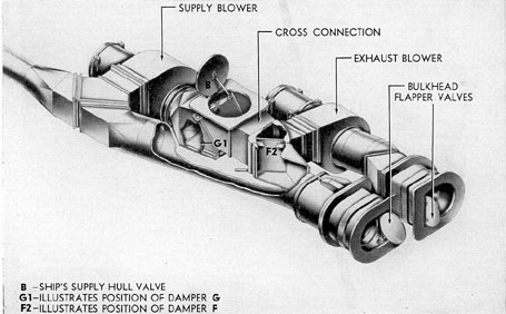
Figure 7-10. Ventilation operation condition No 3.
Figure 7-11. Ventilation operation condition No 4.
90
Figure 7-12. Ventilation operation condition No 5.
Figure 7-13. Ventilation operation condition No 7.
91
Figure 7-14. Schematic diagram of the ventilation system.
92
VENTILATION SYSTEM
TABLE OF OPERATING CONDITIONS
Number of Operation
AIR CONDITION
Position of valve and dampers
Condition of vessel
Condition of ventilation
A
B
C
D
F
G
1. Figure 7-8
Stop
Open
Open
Shut
Shut
F1
G1
On surface, engines STOPPED
Supply from outboard. Exhaust outboard via engine rooms and hatches.
2. Figure 7-9
Run
Open
Open
Shut
Shut
F2
G1
On surface, engines STOPPED
Recirculating and makeup air is from outboard.
3. Figure 7-10
Stop
Open
Open
Shut
Shut
F2
G3
On surface, engines STOPPED
Supply from inboard via hatches and engine rooms. Exhaust outboard via normal supply pipe.
4. Figure 7-11
Stop
Open
Open
Open
Open
F1
G1
On surface, engines RUNNING
Supply from outboard. Exhaust to engine room.
5. Figure 7-12
Run
Open
Open
Open
Open
F2
G1
On surface, engines RUNNING
Recirculating and makeup air is from outboard.
6.
Stop
Shut
Shut
Shut
Shut
F2
G2
SUBMERGED
Recirculating without air-conditioning.
7. Figure 7-13
Run
Shut
Shut
Shut
Shut
F2
G2
SUBMERGED
Recirculating with air-conditioning.
93
7C7. Chart of operating conditions. Valve and damper line-up for various operating
conditions is shown on the chart on the
preceding page. In interpreting this chart it is necessary to know the meaning of the following
symbols which are used frequently:
KEY FOR TABLE OF OPERATING CONDITIONS
Symbol
Meaning
A
Engine induction and ship's supply outboard valve.
B
Ship's supply hull valve.
D
Forward and after engine room, engine induction hull valves.
E
Maneuvering room induction hull valve.
F
Exhaust blower discharge damper.
G
Supply blower suction damper.
POSITION OF DAMPERS
F1
Exhaust blower to discharge into engine room and cross connection shut off.
F2
Exhaust blower to discharge into cross connection and engine room shut off.
G1
Supply blower suction on cross-connection and engine room shut off.
G2
Supply blower suction on cross connection and partial suction on engine room.
G3
Supply blower suction on engine room and cross connection shut off.