16A1. General description. All fuel oil stowage tanks lie between the inner and outer
hulls. There are four normal fuel oil tanks
No. 1, frames 35-41; No. 2, frames 41-46;
No. 6, frames 93-99; No. 7, frames 99-107.
There are six reserve fuel oil tanks: No. 3A,
frames 57-62 starboard; No. 3B, frames 57-62 port; No. 4A, frames 69-75 starboard;
No. 4B, frames 69-75 port; No. 5A, frames
75-80 starboard; and No. 5B, frames 75-80
port. (See FigureA-7.) These six reserve
fuel oil tanks make up the fuel ballast tank
group.
Each tank is connected to three piping
systems: the fuel oil filling and transfer; the
compensating water; and the 225-pound service air system. The 3-inch filling and transfer main, with a main deck filling connection
at frame 33 and another at frame 69, has
two branches to each fuel oil tank, one for
each side of the tank. The 3-inch compensating
water main, with a deck hose connection at
frame 88 and an outlet through a head box,
has a branch to the bottom of each fuel oil
tank. (See FigureA-27.)
Between frames 91 and 93, there are
two tanks: the expansion tank on the port
side and the collecting tank on the starboard
side. Located in the conning tower sheers is
a head box with a vent and overflow which
is kept filled with water from the main engine
circulating water system. A 3-inch line carries
the water from the head box to the bottom of the expansion tank. Another line is
run from the top of the expansion tank to
the 3-inch compensating water main. These
two lines and all branches off the main are
provided with stop valves. Each one of these
stop valves, except for the hose connection,
is kept locked in the open position. The head
of water keeps the tanks completely filled at
all times. Thus provision is made for the
change in volume caused by the variation in
temperature and also for changes in pressure, so that the tank is always equalized
with sea pressure when submerging.
The 3-inch fuel filling and transfer main
has a branch to the bottom of the collecting
tank, and another line is run from the top of
this tank to the engine clean fuel oil tank.
Hence, water under pressure from the head
box passes through the expansion tank, to the
compensating main, and them to the fuel oil
tank being used as the supply. From the
supply tank, oil flows through the transfer
main to the collecting tank and on to the
clean fuel oil tank. The stop valve in the collecting tank supply from the 3-inch transfer
main is locked open; so locked, valves provide
for transfer and compensation under all conditions of operations when a tank, either
normal or reserve, is open to the transfer
main. A supply tank must always be open to
the filling and transfer main, otherwise the
collecting tank is subjected to the depth pressure when submerged.
Filling operations are effected through
the forward and after deck connections described above. The head of oil forces the
water overboard through the deck hose connection for the compensating main or through
the expansion tank and head box.
In case of damage to the head box, pressure is kept on the compensating system by a
line to the compensating main from the main
motor circulating water system in the motor
room. Normal operation requires that the
stop valve in this line be locked shut. This
practice of locking the stop valve during normal operation assures that the compensating
system will operate without drawing water
from the main motor circulating water system.
On the surface, the main engine circulating water system is sufficient to keep the
head box full, thus maintaining a constant
pressure on the expansion tank and from it
to the fuel oil tank on service and the collecting tank. Fuel oil leaving the collecting tank
under the compensating system pressure may
either go to the purifier and from there by
gravity to CFOT, or it stay go to the fuel
transfer and purifier pump. The fuel
163
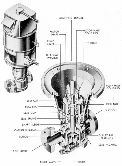
Figure 16-1. Fuel transfer and purifier pump.
164
transfer purifier pump discharges fuel oil to the
main engines. The pump may therefore serve
as a standby for the main engine fuel pump
since the fuel transfer purifier pumps can
take a suction on the line from the collecting
tank to the purifier; the transfer main and
the CFOT discharge this oil directly to the
main engines. The fuel transfer purifier
pumps may also discharge directly overboard.
Purifying is not normally done submerged.
However, if it is, the depth pressure will
maintain a constant pressure on the compensating system.
There are two fuel transfer and purifier
pumps: one in the forward engine room,
supplying clean fuel oil tank No. 1, and one
in the after engine room, supplying clean
fuel oil tank No. 2.
The fuel pump is the positive displacement gear type. A d.c. motor of 1 horsepower furnishes the driving power at 1150
rpm operating speed. This pump has a capacity of 10 gallons per minute.
The operating parts include the valve
body, the rotor and idler, and the relief valve
which is set to open at 45 psi. (See Figure
16-1.)
A bypass line is provided from the transfer main to the fuel transfer and purifier
pump for use in the event of bilging the
collecting tank. Also, a branch from the head
box is run to the compensating main so that
the expansion tank may be bypassed. The
stop valve in each of these lines is normally
locked shut.
The collecting tank is provided with a
drain line to the drain pump for the removal
of water from the bottom of the tank. The
drain pump is provided with a discharge to
the compensating water main to permit pumping the bilges to the top of the expansion
tank, forcing water overboard from the bottom of the tank. This removes the necessity
of discharging bilge water directly overboard.
Valves are provided on the branches from
the transfer main to the deck filling connections for obtaining samples of the oil. Fuel
tanks are provided with a blow and vent
manifold, with blow and vent connections to
each side of the tank from the manifold. The
manifold is provided with gages and relief
valves set at 15 psi. When blowing a fuel
tank, water must leave the tank through the
compensating water main. Balanced hydraulic gages (liquidometers) are installed
in the expansion, collecting, and clean fuel
oil tanks to indicate the oil content.
The connection from the compensating.
water line to the compensating water manifold and to the head box is provided with a
sight glass to check the pipe contents when
filling, blowing, and pumping operations are
being conducted.
The fuel oil tanks and the compensating
water line should be vented frequently to
prevent formation of air pockets. Filled oil
tanks should be vented in the following order
expansion tank, fuel oil tank or tanks in use,
collecting tank. The discharge from collecting tank to clean fuel oil tank should be shut
when venting.
It is essential that all air be excluded
from the fuel oil system, as fuel will not
readily flow past an air pocket under the
small head pressure provided by the head box.
B. RESERVE FUEL OIL TANKS
16B1. General. Fuel ballast tanks Nos. 3A,
3B, 4A, 4B, 5A, and 5B may be used either
as ballast tanks or as reserve fuel oil tanks.
When used for reserve fuel oil tanks, the
fuel ballast tanks must be isolated from the
600-pound main ballast tank blowing system,
and the 10-pound main ballast tank blowing
system. All the blow valves leading to these
tanks from both the 600-pound and the 10-pound blowing manifolds must be secured,
and the flood valves to these tanks locked
shut. This prevents either the compressed
air or the sea water from entering the tanks
and interfering with the proper operation.
of the fuel oil system.
The main and emergency vent valves to
the fuel ballast tanks must also be secured.
Each of the fuel ballast tanks is provided
with one vent valve. Blank flanges are provided for the valve openings in the reserve
165
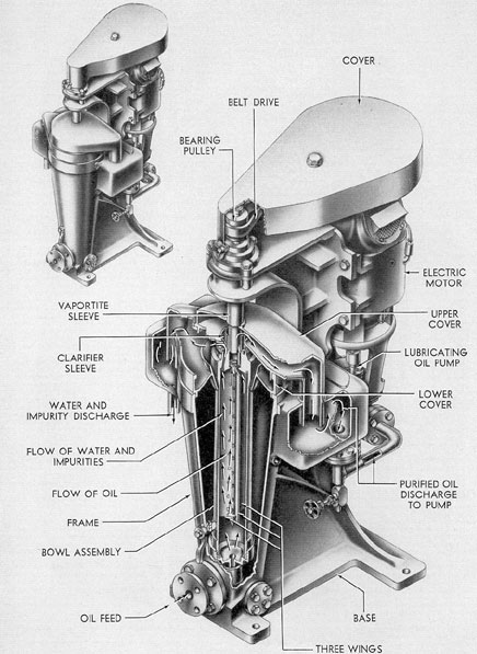
Figure 16-2. Lubricating oil purifier.
166
fuel oil tanks and are to be installed when
fuel is carried in the tank. These blank
flanges are stowed in the superstructure,
adjacent to the vent valves, and the gasket
used with the blank flange is stowed in the
ship.
To attach the blank flange, proceed as
follows: Open the vent valve a slight amount
to relieve the tension on the spring mechanism. Remove nuts, tap bolts, and distance
pieces from studs in the finished face on the
outside of the valve openings. Remove the
pin through the lower end of the bellcrank
and connecting link and put the gasket in
place over the studs. Attach the blank flanges
in place over the studs and replace the nuts
and tap bolts and set up to make a tight joint.
Put the distance pieces in a bag, label them,
and stow in ship. After the blank flanges are
in place, return the operating mechanism to
the locked shut position.
The emergency vent valves for the reserve fuel oil tanks are provided with padlocks. When fuel is being carried in these
tanks, the emergency vents will be locked
shut.
C. LUBRICATING OIL SYSTEM
16C1. General. There are three normal
lubricating oil tanks: No. 1 between frames
79-85, No. 2 between frames 90-96, and No. 3
between frames 107-109. One reserve lubricating oil tank is located between frames
76-77 port. There are four main engine sump
tanks: No. 1 between frames 80-85 starboard, No. 2 between frames 80-85 port,
No. 3 between frames 91-96 starboard, and
No. 4 between frames 91-96 port. There are
two reduction gear sump tanks: No. 1 between frames 103-105 starboard, and No. 2
between frames 103-105 port.
A filling connection is provided on the
main deck between frames 78-79 port; it is
connected by a 2-inch line to a four-valve
lubricating oil filling and transfer manifold
located at frames 78-80 starboard. This manifold is connected directly to each of the normal lubricating oil tanks and reserve lubricating oil tanks.
The tanks are normally filled by passing
the oil through a strainer before it reaches
the manifold; however, this strainer may be
bypassed. The lubricating oil tanks are provided with a blow and vent manifold with
blow and vent connections from the manifold
to each tank. Air is furnished from the 225-pound service air lines through a reducing
valve set for 13 psi and a relief valve set for
15 psi. Oil may be blown from any storage
tank to any other tank; also, oil to be discharged may be blown or pumped overboard
through the deck filling connection or through
a 1 1/2-inch hose connection from the filling
line.
An accessory to the lubricating oil system is the lubricating oil purifying and flushing system. The principal part of this system
is the lubricating oil purifier (See Figure
16-2.), used to separate impurities from the
lubricating oil. There are two lubricating oil
purifiers: one located in the forward engine
room amidships and the other in the starboard forward end of the after engine room.
The major part of the lubricating oil
purifier is a hollow cylindrical rotor called
the bowl, the top part of which is connected
by a coupling nut to a spindle, which in turn
is attached to and suspended from a ball bearing assembly. Three flat plate wings are
spaced radially equidistant inside the bowl.
This three-plate assembly has a cone on the
bottom with which the feed jet comes in contact, thus increasing the liquid flow evenly
and eliminating emulsion formation.
The spindle is belt-driven by an electric
motor fastened on the back of the frame. The
belt tension is maintained by an idler pulley
to assure smooth acceleration.
When the pump is running, the liquid is
jetted into the bowl and, upon coming in contact with the three flat plates, is rotated at
the speed of the bowl. This rapid rotation
causes centrifugal force to act on the liquid,
thus separating the heavier from the lighter
components in the liquid. Solids, sludge, and
water (the heavier parts) are forced through
the oil layer to the outside where they form
a layer on the wall of the bowl.
As the oil in a purified condition reaches
the overflow or discharge port, it is carried
167
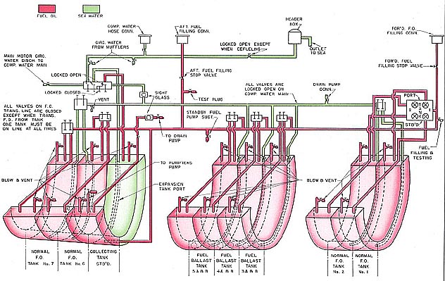
Figure 16-3. Fuel oil system.
to the lubricating oil pump and distributed
to the engines.
The lower end of the bowl is set in a
guide bushing which shifts in accordance with
the position required by the center rotation
of the bowl.
The lubricating oil purifying and flushing system may be used to perform the following functions:
1. Flush engines prior to starting.
2. Purify the lubricating oil.
3. Supply engines with lubricating oil.
4. Clarify the lubricating oil.
Clarification of the lubricating oil is
accomplished by the Sharples centrifuge
which also serves as the fuel oil purifier just
described. The machine is set up as a clarifier by installing a clarifier sleeve or ring
dam on the top of the bowl, thus closing the
outlet passage through which the water is
discharged. The term clarifier is applied to
the machine when it is set up to discharge a
single liquid from which solid matter has
been removed by centrifugal force. If the
machine is set up to separate two liquids
from solid matter and from each other (such
as oil and water in a fuel oil purifier), it is
called a separator. The machine is usually
set up as a separator for fuel oil purification
and a clarifier for lubricating oil purification.