14A1. General. Hydraulic power is used to
tilt the bow and stern planes. Each system
(bow and stern planes) has its own power
supply system. Except in emergencies, the
power facilities in each system are adequate
for its own individual operation without reliance on power from the main hydraulic
system.
The control units for diving and rising
are assembled in a diving control stand
located in the control room. There is a set
of controls for stern plane tilting, a set for
bow plane tilting, and control valves for bow
plane rigging. The control panel has diving
indicators, gages, and motor switches.
Three methods of plane tilting are available at the control panel, based on three
different sources of hydraulic power. They
are designated as follows:
1. Power, in which the power is independently developed in each plane
tilting system by the motor-driven
Waterbury A-end pump belonging to
that system.
2. Hand, in which the power is developed in the diving control stand
pump, connected to each system, by
the manual efforts of the diving stand
operator.
3. Emergency, in which the power is
obtained from the main hydraulic
system.
Emergency is used only when normal
power fails. Hand power is employed when
the other two power sources are, inoperative,
or when silent operation of the submarine
is necessary to avoid detection by the enemy.
In addition to bow and stern plane tilting, this chapter also contains a description
of bow plane rigging. A schematic view of
the bow and stern planes systems and their
associated equipment is illustrated in FigureA-21.
B. BOW AND STERN DIVING GEAR
14B1. Bow planes. Each plane is carried on
a separate stock. The mechanism for tilting
planes consists of a hydraulic cylinder and
piston arrangement connected by a connecting rod to the tiller,
the latter being mounted
on and secured by clamping and doweling to
the hexagonal-shaped end of each plane stock.
The planes are actuated between stops, allowing a total travel of 54 degrees of 27 degrees
each side of zero tilt.
14B2. Stern planes. The horizontal athwartship
for the stern diving planes is keyed to
a tiller which is operated through an angle
of 54 degrees by a connecting rod, cylinder,
and piston arrangement located in the after
torpedo room under the non-watertight walking flat.
The bow and stern diving gears are of
the electrohydraulic type and under normal
operation the planes are tilted by power. The
hydraulic pump are the Waterbury type, size
5 A-end, connected by a flexible coupling to
an electric motor of 7.1 hp at 350 rpm constant speed.
These units are located in the
forward and after torpedo rooms respectively.
The motor of the electrohydraulic system is started and stopped by a push button
type switch, and provided with an electrically
operated brake which grips the armature
shaft when the motor is not being operated.
An interlock switch, controlled by operation
of the change valve at the operating station
in the control room, prevents starting the
motor except when the change valve is in
Power position.
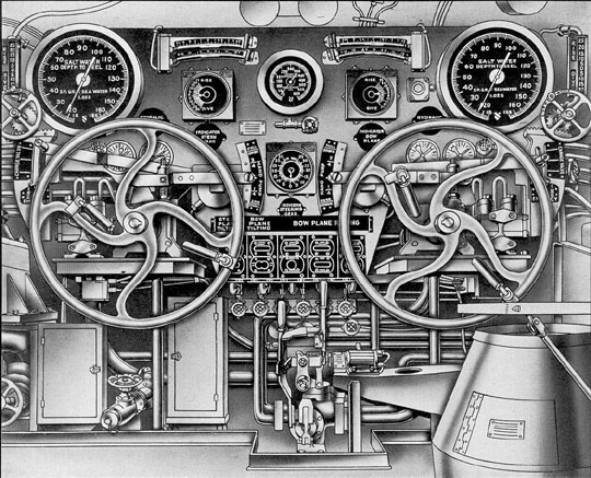
In the control room at the operating
station, a handwheel is connected to another
hydraulic pump. (See Figure 14-1.) Rotating
the handwheel with the change valve set for
Power forces oil to control cylinders at the
electrically driven pump. This actuates the
156
control shaft on the pump by means of a
rocker shaft and bell crank, thereby controlling the direction of flow and quantity of
oil. Thus, the direction and amount of tilt
are governed by the rotation of the handwheel of the diving station; to the right for
Dive and to the left for Rise. The handwheel
should always be brought back to its original
position to stop further movement of planes;
this also allows the centering device, consisting of a double-acting spring, to hold the
pump control shaft in its neutral position.
C. OPERATIONS
14C1. Power tilting of planes. When tilting
the bow or stern planes by power, the change
valve for that plane must be in the power
position. The stroke adjuster is set for one-quarter of a stroke and the hydraulic pump
motor is started at the diving station.
When the station is set for power tilting,
turning the wheel delivers oil to the control
cylinder which actuates the tilting box of the
power-driven hydraulic pump. Tilting the
box of a power-driven hydraulic pump causes
it to deliver oil to the tilting ram.
When the wheel is turned clockwise, oil
is delivered for dive angle on the planes;
when the wheel is turned counterclockwise,
oil is delivered for rise angle on the planes.
(See FigureA-22.)
14C2. Hand tilting of planes. In tilting the
bow and stern planes by hand, the electrohydraulic system is stopped and the change
valve at the diving station is set for Hand;
rotating the handwheel forces oil directly to
the hydraulic cylinder located in the forward
torpedo room for bow planes, and the after
torpedo room for stern planes.
The bow plane setup is the same as the
stern plane setup for hand tilting except that
the hand rigging and tilting control valve is
used on bow plane tilting to direct the oil to
the rams (FigureA-23) when set in the tilt
position.
14C3. Emergency tilting of planes. Provision
is made for tilting the planes with the main
hydraulic system by setting the change valve
at the diving station in the Emergency position. The direction of oil flow for tilting the
planes is then controlled by the emergency
control valve.
The bow and stern planes have separate
control valve handwheels for emergency operation. While the handwheels operate
similarly, they are not interconnected and must
be individually operated.
Turning the emergency control valve
handwheel clockwise directs oil from the main
hydraulic system directly to the stern plane
ram in the after torpedo room and the bow
plane rain in the forward torpedo room. The
oil flow will be for dive. Turning the control
valve handwheel counterclockwise admits oil
to the stern plane ram and the bow plane ram
for rise. (See FigureA-25.)
14C4. Plane angle indicating system. The
plane angle indicating system is of the selsyn
type. The bow plane transmitter is located
in the forward torpedo room and is driven
from the starboard plane stock by a gear segment and pinion. The stern plane transmitter
is located in the after torpedo room and is
driven by an arrangement of levers and links
from the plane tilting piston rod. The indicators are mounted on the diving station
panel in the control room, In addition, an
auxiliary plane angle indicating system is
provided which indicates the degree of rise
or dive on the planes in 5-degree intervals.
A mechanical plane angle indicator is provided in the forward torpedo room and two
plane angle indicators in the after torpedo
room, one on the after bulkhead and one at
the tilting cylinder beneath the platform deck.
14C5. Stern diving gear and capstan motor.
The stern plane tilting motor, located in the
after torpedo room, is also used to operate
the after capstan by a silent chain drive with
the sprocket mounted between the motor and
the hydraulic pump. The chain is removable
and can be dissembled by removing a special
pin from the links. The stern plane tilting
hydraulic pump cannot be cut out when the
capstan is in use; therefore, the pump control shaft should be in the neutral position
to prevent the movement of the planes.
157
Figure 14-1. Diving control station
158
14C6. Stern plane drift stop. The position
at which zero lift occurs with relation to the
stern planes is with the planes set at 4 degrees
in the rise, direction; the position at which
minimum drag occurs is with the planes set
at 2 1/2 degrees in the rise direction. Therefore,
it is desirable that the indicator in the
control room read zero when the planes are
set at 4 degrees in the rise direction, because
in that position the lift, when operating submerges,
is zero. It is also desirable that when
operating on the surface, the planes be set
at that angle at which a minimum of drag or
resistance is encountered. In order to obtain
a setting of 2 1/2 degrees rise while operating
on the surface, the indicator in the control
room should read 1 1/2-degree dive.
When cruising on the surface under normal conditions,
a drift stop is provided to
prevent the stern planes from passing beyond
the 2 1/2, degree rise position. This drift stop
is located at about the midstroke of the end
of the piston rod extension in the after torpedo
room. A bar is provided to be lifted in
the path of the end of the piston rod extension
when the planes are approaching the
2 1/2-degree rise position blocking the path and
thus preventing the rod extension from moving
farther in the rise direction. The planes
must be moved in the dive direction until the
indicator (in the control room) reads at least 5
degrees dive before the stop bar can be
lifted into position. A pin in the rod extension
enters a hole in the bar as the planes are
moved to the 2 1/2-degree rise position. The
stop bar is released by moving the planes in
the dive direction until the indicator (in the
control room) reads at least 5 degrees dive,
disengaging the pin from the stop bar and
allowing the bar to drop clear of the path of
extension rod.
14C7. Bow plane rigging arrangement. The
bow planes are rigged out for tilting operation by the windlass and capstan hydraulic
motor, a Waterbury size 10 B-end normally
driven from the main hydraulic system
through the rigging control valve. Provision
is also made for rigging the planes by hand
from the diving station by setting the change
valve to Hand, the rigging control valve to
Neutral, and the hand rigging and tilting
control valve to rig. (See FigureA-24.)
Rotating the bow diving handwheel to the
right will rig out the planes. A hand-operated
clutch is provided for windlass and capstan
or plane rigging operation and is located in
the forward torpedo room. With the clutch
set for bow rigging operation, the hydraulic
motor drives a vertical shaft through a reduction
gear and worm gear arrangement.
This shaft passes through the hull to the
outside where bevel gears and shafting operate two
pairs of 39 1/4-inch diameter spur
gears. These gears are mounted in pairs
athwartships and fore and aft, so that the
forward and after gear of each pair carry at
a point on the circumference the pin for the
crank end of the plane rigging connecting
rod. The gears are rotated 181 degrees 41" between
mechanical stops when raising the planes
from the horizontal to the housed position.
At the lower end of the vertical shaft, an
indicator switch is driven by bevel gears; this
indicates the rigged in or rigged out
position by telltale lights at the diving station.
14C8. Rigging and tilting interlocks. At the
lower end of this same vertical shaft, the
rigging interlock switch, driven by bevel
gears, prevents the operation of the electrohydraulic
bow plane tilting motor except when
the planes are in the fully rigged-out position.
There is also a hydraulic interlock valve
which prevents the flow of oil to the plane
tilting cylinder from the hand or emergency
control valve until the planes are in the fully
rigged-out position. The operating mechanism
for this interlock valve is also driven by
bevel gears from the vertical shaft, and the
bow plane rigging indicator is mounted on
the underside of the casing. If the sheer pin
drive at the lower end of the pointer shaft
fails, the interlock valve may be operated by
applying the T-handled socket wrench to the
squared lower end of the shaft extending
through the pointer hub. This wrench is
stowed on the underside of the worm gear
unit adjacent to the valve operating mechanism.
In addition, there is also a regulating
control valve operated from the same shaft.
The purpose of this valve is to restrict the
flow of oil to the hydraulic motor when the
159
bow planes are nearly rigged out or nearly
housed. The flow is not completely cut off;
a small amount is bypassed to permit the
planes to creep into the stops located on the
large spur gears. There is also a lock on the
rigging control valve operated by a solenoid;
this prevents the housing of the bow planes
unless the planes are within 1 1/2 degrees
either side of zero tilt, and then only by manually
operating the push button which releases the lock.
An additional release of the
solenoid lock is also provided for emergency
use and is accomplished by means of a lever
located in the armature end of the solenoid.
This means of disengaging the solenoid lock
should be used for rigging out planes only in
case they have been thrown off the position
for rigging as a result of wave slap.
The diving gear control stations, bow
and stern, are located together on the port
side of the control room. (See Figure 14-1.)
They are provided with an 8 1/2-inch depth
gage reading to 450 feet and a rudder angle
indicator. Each station is provided with an
electrical self-illuminated selsyn type plane
angle indicator, an auxiliary plane angle indicator
reading at 5-degree intervals, a 16-inch depth gage reading to 165 feet, and a
pair of spirit trim indicator inclinometers for
angles from 0 degrees to 5 degrees and from
0 degrees to 15 degrees.