13A1. General. The rudder of the submarine is moved by hydraulic power. Under
normal operation, the steering system has
its own source of power, a motor-driven size
5 Waterbury A-end pump, and is, therefore,
except in emergencies, completely independent of the main hydraulic system described
in Chapter 12.
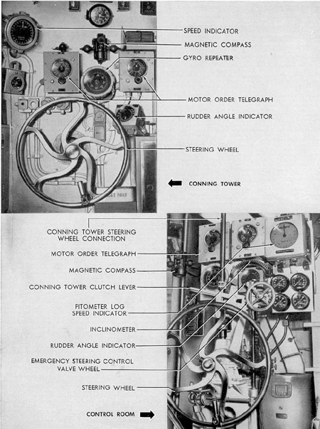
The principal control units are assembled
in the steering stand, located in the control
room. However, since there is a steering
wheel in the conning tower connected to the
steering stand controls by a shaft, the submarine can be steered either from the control
room or from the conning tower. To allow
for every contingency, the steering system is
so planned that three different methods of
steering are available, based on three different sources of hydraulic power. They are
designated as follows:
1.
Power, in which the hydraulic power
is independently developed by a
motor-driven pump belonging to the
system itself.
2.
Hand, in which the hydraulic power
is developed in the steering stand
pump by the direct manual efforts
of the steersman.
3.
Emergency, in which the hydraulic
power is supplied by the main hydraulic system.
It should be emphasized that the rudder
itself is moved by hydraulic power in all three
cases; the only difference between these
methods is in the manner in which the power
is developed.
Emergency power is used only when the
normal power (called simply Power) fails.
Hand power is used only when silent operation of the submarine is necessary to avoid
detection by enemy craft, or when both the
normal Power and the Emergency power
from the main hydraulic system have failed.
The submarine can be steered by all
three methods from either the control room
or the conning tower.
B. DESCRIPTION
13B1. General arrangement. The steering
system as a whole is shown in FigureA-20.
The system may conveniently be thought of
as divided into four principal parts:
a. The normal power supply system,
comprising a Waterbury size 5 A-end pump,
the motor which drives it, the control cylinder, and the main manifold.
b. The steering stand, comprising the
main steering wheel, emergency handwheel,
steering stand pump, pump control lever,
change valve, emergency control valve, conning tower connecting shaft, and a clutch.
c. The main cylinder assemblies, comprising the cylinders and plungers and the
mechanical rudder-angle indicator.
d. The rudder assembly, comprising the
connecting rods and guides, the crosshead,
on the rudder itself.
13B2. Detailed description.The normal
power supply system. The Waterbury speed
gear. The actuation of the various hydraulically operated units on board a submarine
often requires great precision of control and
the transmission of power at variable speeds
and pressures, without any sharp steps or
graduations. The hydraulic machine used for
many of these operations is the Waterbury
speed gear, a mechanism which furnishes
instant, positive, and accurate hydraulic
power transmission.
The Waterbury speed gear may be used
as a pump (converting rotary mechanical
motion into hydraulic fluid displacement) or,
with one important modification of internal
structure, as a hydraulic motor (converting
hydraulic fluid displacement into rotary
mechanical motion).
145
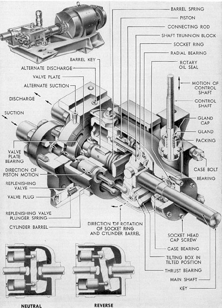
The type of Waterbury speed gear generally used as a pump is designated as a
Waterbury A-end speed gear (Figure 13-1).
The type used exclusively as a hydraulic
motor is designated as a Waterbury B-end
speed gear or Waterbury B-end hydraulic
motor. The A-end type is in one special installation used as a hydraulic motor, but,
since this is not generally the case, it will be
convenient to describe the A-end type primarily as a hydraulic pump.
A-end and B-end speed gears are often
used together to form a pair of power transmission units separated by any required
length of hydraulic piping to suit the particular installation needs. So used, they receive rotary mechanical motion from an electric motor at one point and transmit it as
fluid displacement any required distance,
where it is reconverted into rotary motion
with a positiveness and fineness of control
that could not be achieved by the use of electric motors alone.
Waterbury A-end speed gear, used in the
submarine hydraulic system primarily as a
pump, is designated as size 5-A. Two sizes
of B-end motors are used, designated respectively as 5-B and 10-B.
The Waterbury A-end pump is operated
by a rotating shaft which may be driven
either by an electric motor or by hand. Three
motor-driven and three hand-driven Waterbury A-end pumps are used in a submarine:
one of each type in the, steering system, stern
plane system, and bow plane system, respectively. In operation by normal power, the
two types are used in each system as a team;
the motor-driven unit transmits oil or the
power actuation of the system, while the
hand-driven unit, fitted with a large handwheel and designated as a telemotor, or steering stand pump, transmits oil to a control
cylinder to provide fine control of the output
of the motor-driven units. The hand-driven
unit is also used, alternately, to operate the
system by hand whenever it is desired not to
use the motor-driven pump.
Although the Waterbury A-end speed
gear is activated by rotary motion, in principle it is actually a reciprocating multiple
piston type of pump. It consists of a casing
containing three basic elements:
1. A socket ring, which holds the ball
sockets of the seven or nine piston connecting
rods arranged in a circle around the driving
shaft.
2. A cylinder barrel, in which are bored
the seven or nine corresponding cylinders.
3. A tilting box, which alters the angle
and direction of the socket ring with respect
to the cylinder barrel.
The socket ring and cylinder barrel are
mounted on the drive shaft so that they rotate
together. The socket ring is sea arranged that
it can be made to rotate either parallel to the
cylinder barrel or at an angle to it. Connected to the tilting box is a control shaft
extending through the pump casing, which,
when pushed up or down, determines the
angle and direction of the tilting box.
Reference to Figure 13-1 will help to
clarify the manner in which pumping action
is obtained. The socket ring rotates within
the tilting box on the radial and axial thrust
bearing. As long as the tilting box is maintained in the vertical position, the socket ring
and cylinder barrel rotate parallel to each
other, and there is no reciprocating motion
of the pistons within the cylinder barrel.
However, when the tilting box is tilted in
either direction away from the vertical, the
socket ring no longer rotates in the same
plane, as the cylinder barrel. This means that
as a ball socket on the socket ring reaches
that point in its rotation which is closest to
the barrel, the piston belonging to it will be
driven down into the corresponding cylinder,
and then, as this same ball socket recedes to
the point farthest away from the barrel, the
piston will again be withdrawn.
The diagrams on the lower part of Figure, 13-1 showing the tilting box tilted away from
the vertical, and illustrate the course of a
single piston, whose motion we are able to
follow as the socket ring turns through half
a cycle (180 degrees).
As the piston rises to its uppermost position, it occupies a progressively smaller space
in the cylinder until it reaches the point at
which the socket ring and barrel are farthest
apart. The partial vacuum which is produced
in the chamber by the outward movement of
the piston draws the fluid into the cylinder
by suction.
146
Figure 13-1. Waterbury speed gear.
147
In the intermediate position, the piston
returns into the cylinder and begins to displace the fluid accumulated there. At its lowest point, the piston occupies almost the entire
cylinder. The expulsion of the fluid through
the discharge port is now complete. The
piston again rises from this position for the
suction stroke. The repetition of these movements in sequence by all of the pistons results
in a smooth nonpulsating flow of hydraulic
fluid.
In normal operation, the hydraulic power used by the steering system is developed by
a Waterbury size 5 A-end pump. It is driven
by a 1.5-hp electric motor at a constant speed
of about 440 rpm. The pump turns in a clockwise direction as viewed from the, motor end
of the shaft. The pump's speed is constant;
only the direction and angle of the tilting box
change. It is these that determine the amount
of oil that is pumped into the system to move
the rudder and the direction in which it is
pumped.
b. The control cylinder. The function
of the control cylinder is to translate the
movement of the main steering wheel, as the
steersman turns it left or right, into a corresponding upward or downward motion of the
control shaft, thereby changing the position
of the tilting box in the motor-driven Waterbury pump. This, in turn, varies the stroke
of the pistons inside the motor-driven pump.
It also determines the quantity and direction.
of flow of the oil that is pumped to the main
rams. In this manner it controls the output
of the motor-driven Waterbury pump in
obedience to the actions of the steersman
when steering by normal power.
The control cylinder assembly consists
of a pair of small hydraulic cylinders opposed
and axially in line, having in common a
single plungers which slides between and
through the cylinders. Bell-crank linkage
connects this plunger to the tilting box.
On all later classes of submarines, the
control shaft that extends through the Waterbury A-end power-driven pump has the centering spring attached to one end of the control shaft and the control cylinder on the
opposite end.
The pump control shaft enters at the
bottom, connected to the tilting box. The
centering spring and its actuating spindle,
against which the top end of the pump control shaft bears, are contained in the tall,
pipe-like housing screwed onto the top of the
power-driven Waterbury A-end pump.
13B3. The steering ram cutout manifold. The
steering ram cutout manifold consists of a
multiple-port housing containing nine valves
built into the body, and eight ports which
connect the main rams to the sources of hydraulic power.
The manifold is so arranged that the
four center valves are power cutouts to the
port and starboard rams from the main steering pump. The forward set of two valves
and the after set of two valves are hand and
emergency cutouts to the port and starboard
rams when the power is furnished from the
control room. A bypass valve at the top central part of the manifold, if opened, would
bypass the main steering pump by connecting
both sides of the pump together. This bypass
normally is shut.
The manifold has two connections at the
top which connect the manifold with the
motor-driven Waterbury A-end pump. Of the
lower four connections of the manifold, the
two in the center are connections to the starboard ram. The remaining two connections,
one forward and one aft on the lower part of
the manifold, are hand and emergency connections from the control room.
The connections from the manifold to the
port ram are at the foremost and aftermost
part of the manifold. All the valves have
attached name plates indicating their purpose.
The main cylinder ram assemblies, usually referred to as the rams (port and starboard), transform hydraulic power into
mechanical power to move the rudder. Each
consists essentially of a pair of hydraulic
cylinders opposed and axially in line, having
in common a plunger or ram that slides between and through them and a hydraulic port
at each end, into which oil is admitted to
move the rams forward or aft. The plunger
has at its center a heavy yoke forged
148
Figure 13-2. Steering stand.
149
integrally with it; the yoke has a hole drilled
in it to take the inboard connecting rod
which is locked into it at this point by heavy
lock nuts, one on each side of the yoke. The
inboard connecting rod slides through the
bearings. Oil leakage past the plunger is
prevented by the packing. The entire ram
assembly is bolted to the framework through
the brackets.
Mounted at the forward end of the ram is
the mechanical rudder-angle indicator pointer
showing the angle of rudder deflection on the
indicator dial, which is graduated in degrees.
An electrically operated rudder angle transmitter is located on the other ram. It transmits the angle of deflection electrically to a
rudder angle indicator on the instrument
hoard in the control room.
13B4. The steering stand. The hydraulic
power that moves the rudder is directed by
the steersman from the steering stand, an
assembly which contains the control equipment for all three methods of steering, Power,
Hand, and Emergency. (See Figure 13-2.)
a. The steering stand pump. Since, in
operation by normal power, it is the direction of the motor-driven Waterbury A-end
pump tilting box that determines which way
the rudder moves, and since the position of
this tilting box is controlled by the movement
of oil in the control cylinder, it is clear that
to steer the submarine, some device is needed
which will drive that oil one way or the
other as desired. The mechanism must be one
that will respond readily to the steersman's
touch, yet control accurately the powerful
pressures developed by the motor-driven
Waterbury A-end pump. Such a device is the
steering stand pump, the steering stand's
main unit. The steering stand pump is actually a hand-operated Waterbury A-end pump. A bracket is fitted externally to it and the
pump control shaft so that its tilting box
always tilts in the same direction, though its
angle, that is, the degree of tilt, may be
changed. Consequently, the flow of oil depends solely on which way its shaft is rotated.
If a large handwheel is fitted to this shaft,
the ports of the pump connected to opposite
ends of the control cylinder, turning the wheel
left or right, will then pump oil to one or the
other end of the control cylinder, which in
turn tilts the tilting box in the motor-drivers
Waterbury A-end pump, thus moving the
rudder left or right. Therefore, turning a
wheel fitted to the shaft of the steering stand
pump will steer the submarine.
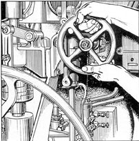
b. The main steering wheel. This wheel
is mounted vertically at the after end of the
steering stand. It is used for both POWER
and HAND steering.
As hand steering requires greater effort,
a retractable spring handgrip is built into
the rim. During power steering, this handgrip may be kept folded in.
A spring-loaded locking pin is built into
the hub; when pulled out, it allows the main
steering wheel to be disengaged from its
shaft.
This is provided to prevent the main
wheel from spinning heedlessly when the
submarine is being steered from the conning
tower.
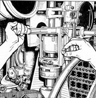
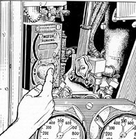
C. OPERATIONS
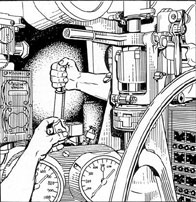
13C1. Power steering. When steering by
power, (See Figures 13-3 to 13-7.) the following conditions are obtained:
a. The change valve in the control room
is set for power steering.
b. The steering stand pump stroke control lever may be in any of the possible positions. Experience has indicated, however, that
the most satisfactory position is with the
pump at approximately three-quarters of a
stroke.
c. The main steering motor is running.
To illustrate the operation of the steering gear when steering by power, assume that
it is desired to move the rudder from amidship to hard over left rudder. The steersman
turns the steering wheel to the left, thereby
turning the shaft of the steering stand pump
which delivers oil through the change valve
and one of the control cylinder lines to the
after control cylinder; and oil from the forward control cylinder is forced back through
150
Figure 13-3. Change valve.
the other control cylinder line to the suction
side of the pump.
Delivery of oil to the after control cylinder moves the control ram forward, thereby
moving the main pump tilting box control
shaft downward from neutral toward full
stroke. This puts the tilting box in a position
to deliver oil from the port side of the pump
through the relief and cutout manifolds. Oil
from the manifolds enters the lines to the
forward starboard ram and the after port
ram, moving the rudder to the left, while
return oil from the forward port and after
starboard ram is delivered to the starboard
side of the pump or the suction side.
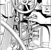
Figure 13-4. Stroke adjuster.
Figure 13-5. Shifting steering control.
For the purpose of maintaining the pump
control shaft in neutral position when it is
desired to hold the rudder angle constant, a
spring-loaded centering device is mounted
adjacent to the pump. This device consists
of a compression spring enclosed in a cylinder
and mounted on a spindle in such a way that
if the spindle is moved in either direction,
the spring is compressed and tends to return
the spindle to its normal position. The spindle
is connected to a lever mounted on the rocker
shaft which operates the levers to the pump
and control cylinders respectively.
When the desired position of the rudder
is reached, the steering wheel must be brought
Figure 13-6. Steering wheel.
151
Figure 13-7. Starting control.
back to its original position to stop rudder
movement, since there is no follow-up mechanism in this steering gear.
The power steering gear is protected by
two relief valves, one installed in either side
of the main relief manifold.
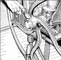
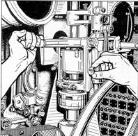
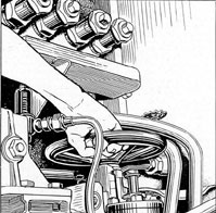
13C2. Hand steering. When steering by
hand, (See Figures 13-8 to 13-12.) the following conditions are obtained:
a. The main Steering pump aft is
stopped.
b. The change valve in the control room
is set for hand operation.
c. The steering stand pump stroke lever
Figure 13-8. Starting control.
Figure 13-9. Change valve.
is set in its aftermost position in order to
obtain a maximum delivery of oil and therefore maximum speed of rudder travel under
the condition of hand steering.
Again, assume that it is desired to move
the rudder from amidships to the hard over
left position. The steering wheel is turned
left. Oil is delivered by the steering stand
pump directly to the forward starboard ram
and after port ram. The rudder moves to the
left. Oil from the after starboard ram and
the forward port ram returns to the suction
side of the steering stand pump. The rudder
moves so long as oil is delivered to the rams
Figure 13-10. Stroke adjuster.
152
Figure 13-11. Shifting steering control.
Figure 13-12. Steering wheel.
by turning the steering wheel and thus
driving the steering stand pump.
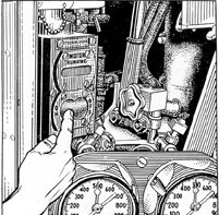
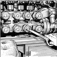
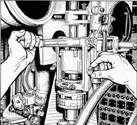
13C3. Emergency steering. Provision is
made for steering by direct delivery of oil to
the main rams from the main hydraulic system. Oil is delivered from the main cutout
manifold to the steering stand. The emergency steering control valve on the steering
stand is a piston type control valve. Oil
returns from this valve to the return and
low-pressure side of the main cutout manifold. Movement of the control valve handwheel for right rudder causes the oil under
pressure from the main cutout manifold to be
delivered to the forward port and after starboard rams while at the same time, oil is
returned from the after port and forward
starboard rams through the control valve to
the return side of the main cutout manifold.
Movement of the control valve handwheel
for left rudder causes the oil to be delivered
to the after port and forward starboard rams
while, at the same time, oil is returned from
the forward port and after starboard rams
through the control valve to the return side
of the main cutout manifold.
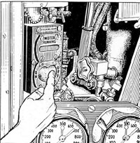
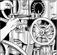
When steering by emergency power, the
change valve should be set in the emergency
Figure 13-13. Starting control.
Figure 13-14. Change valve.
153
Figure 13-15. Main cutout manifold.
position. The emergency cutout valves in the
hand and emergency cutout manifold should
be opened and the hand cutout valves should
be shut. When the desired position of the
rudder is reached, the handwheel must be
brought back to neutral to stop rudder movement and to hold the rudder in the desired
position. Arrangement is provided to connect
the emergency control valve lever to the vertical steering shafting by a removable link,
thereby making it possible to steer by the
emergency system from the conning tower.
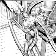
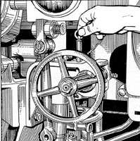
When emergency steering from the
Figure 13-16. Emergency steering pin.
Figure 13-17. Emergency steering wheel.
conning tower, the handwheel control (in control room) must be disengaged. A clutch is
provided for this purpose and must be engaged except when the link is connected for
emergency steering from the conning tower.
To steer by emergency from the control room,
this removable link is not connected and the
emergency steering control valve is moved by
the handwheel. A locking pin is provided to
hold the control valve in the neutral position
when emergency steering is not being used.
(See Figures 13-13 to 13-20.)
The electrical rudder angle indicating
system is of the selsyn type. The rudder
Figure 13-18. Emergency control valve lock.
154
Figure 13-19. Shifting steering control.
angle transmitter is located in the after torpedo room on the port side and is driven
through a rack and pinion from the port
steering ram connecting rod. There is one
rudder angle indicator in each of the following locations: the bridge, the conning tower
Figure 13-20. Emergency connecting link.
steering station, the control room steering
station, the control room diving station.
A mechanical rudder angle indicator,
driven also from the port steering ram connecting rod, is located in the after torpedo room.