Submarine listening equipment is designed to
receive and reproduce underwater sounds-both
sonic and ultrasonic-for the purpose of identifying
the sounds and locating their sources. Sonic
sounds (below 15,000 cycles per second) are made
by propellers, engines, rudder motors, pumps,
gear wheels, and many other devices. Ultrasonic
sounds originate mostly from high-speed propellers.
The bearings of the sources of sounds usually can
be determined, so that targets can be located without the use of echo-ranging gear.
The original J-series listening equipment was
designed for use on submarines. Most modern
listening equipment, such as the JP and JT, is
designed for patrol craft, picket boats, and submarines. The JP-series listening equipment is
now in use on submarines as a unit of the JT equipment.
The JP is a sonic equipment-that is, it receives
audible sounds, amplifies them, and applies them
to either headphones, loudspeakers, or a tuning-eye indicator. Because the line hydrophone used
with the JP is moderately directional, bearings on
the sound sources can be made by use of the tuning-eye indicator. The JP equipment was designed
for small surface craft. The JP-1, JP-2, and
JP-3 are used on submarines.
Although the JP is a complete sonic listening
equipment, it is now used on submarines only as a
part of the JT equipment. The JT equipment
uses a directional line hydrophone to receive both
sonic and ultrasonic noises. The JT uses the JP
amplifier and indicator practically unchanged. In
addition, the JT has (1) a beat-frequency converter for converting ultrasonic sounds into audible
frequencies and (2) a right-left indicator for
taking accurate bearings on sonic sounds. The
JP and JT equipments are described in this
chapter, as is the JAA triangulation-listening-ranging equipment.
The JAA equipment consists of two line-type
hydrophones and their associated amplifiers. One
hydrophone is mounted on the forward end of the
submarine and the other on the after end. Either
hydrophone can be used independently to locate
targets by listening, or both hydrophones can be
used simultaneously on one target. When both
are used, the range of the target can be calculated
by triangulation of the sound emitted from the
target vessel. The JAA bearing-indicating units
are similar to those of the JT.
This chapter discusses not only the JP, JT, and
JAA listening equipments but also the following
accessories to submarine listening equipments:
(1) The noise-level monitor and cavitation indicator, which checks the noise level and the cavitation noise originating from own ship; and (2) the
underwater telephone, which furnishes voice communication between underwater craft and other
ships.
Model JP Listening Equipment
DESCRIPTION
Models JP-1, JP-2, and JP-3 equipments are
used on submerged submarines to obtain bearings
on other vessels by directional detection of underwater
sounds. They can be used also to listen for
own ship's noise. Models JP-2 and JP-3 differ
from JP-1 in the amplifier circuits. Models JP-2
and JP-3 are alike except for the method of mounting the hydrophone.
241
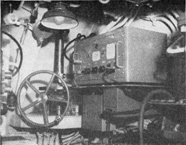
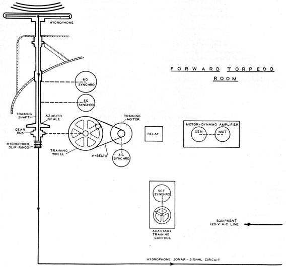
Figure 13-1 -Model JP-3 listening equipment.
In figure 13-1 the JP-3 receiver and training
handwheel are shown mounted in a forward torpedo room. The hydrophone, which is not shown
in figure 13-1, is mounted topside on a shaft
operated by the handwheel. The training is
manual.
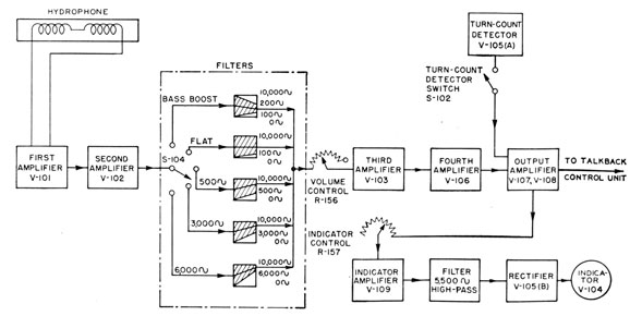
The block diagram of the JP is shown in figure
13-2. With the aid of the tuning-eye indicator on
the amplifier, the operator can train on a noise
source with an accuracy of ±1 ½°. Relative bearings are read from a dial at the handwheel, as
shown in figure 13-1.
Hydrophone
The hydrophone is not retractable. It is a
directional line-type hydrophone 3 feet long. It is
magnetostrictive and is polarized by permanent
magnetization. Its frequency response is from 100
to 40,000 cycles per second. Because the hydrophone is mounted topside, the JP is sometimes
referred to as "topside" listening gear.
Receiver
Figure 13-3 shows the circuit of the JP-1 audio
amplifier with a line filter. The amplifier consists
of four voltage amplifier stages and a power amplifier stage. The response is flat from 200 to 15,000
cycles per second. The amplifier response is still
good above 20,000 cps, but the limit of audibility
is about 15,000 cps.
The filter between the second and third amplifier
stages is an RC filter that attenuates either high
frequencies or low frequencies in five combinations.
The filter switch, 5104, is a multiple constant
selector switch having four sections. This switch
has five positions, marked "bass boost," "flat,"
"500~" "3,000~" and "6,000~" The bass
boost filter reduces high frequencies to give a
preference in response to frequencies near 150 cps.
The flat filter gives a response that is essentially
flat from 200 to 15,000 cps. The 500-cycle filter
attenuates low frequencies and passes high
Figure 13-2 -Block diagram of the JP listening equipment.
frequencies above 3,000 cps without much attenuation. The 3,000-cycle filter attenuates frequencies
below 3,000 cps more sharply than the 500-cycle
filter. The 6,000-cycle filter passes only a narrow
band of frequencies in the vicinity of 6,000 cps.
The flat alter is used normally when the operator
is searching for a noise source. After a noise
signal is received, one of the filters is selected to
pass most of the noise signal and reject most of
the unwanted background noises that are always
present. The choice of filter depends on the
frequency components of the signal.
The output amplifiers are two 6G6G tubes in
push-pull. The output can be connected to
loudspeakers, to headphones, or to an intercommunication "talkback" unit for relaying the
output to the conning tower.
The output is connected also to the indicator-amplifier stage, V109, which further amplifies the
signal. The signal then is passed through a high-pass filter, which greatly attenuates all frequencies
below 6,000 cps. The high-frequency output of
the filter is rectified and applied to the grid of the
tuning-eye indicator. Only high frequencies are
used because the directivity of the hydrophone is
not adequate for low-frequency signals.
The stage marked "turn-count detector" in
figure 13-2 is simply a diode that clips off the
peaks of the signal input to the output amplifiers.
The resulting distortion sometimes causes periodic
noises, like propeller sounds, to stand out distinctly from water noises so that the operator can
count the number of propeller beats per minute.
Model JT Listening Equipment
COMPONENTS
The model JT is a directional listening system
designed to detect, identify, and locate sources of
both sonic and ultrasonic sounds. It is designed
to use the JP sonic equipment and has a super-sonic converter so that ultrasonic as well as sonic
sounds can be amplified by the JP amplifier. In
addition, it has a more directional hydrophone
than the JP hydrophone and has a right-left
indicator (RLI) for taking bearings on sonic
sounds with greater accuracy than is possible with
the tuning-eye indicator of the JP equipment.
An interphone-amplifier unit permits "talkback"
between the forward torpedo room-in which the
JT system is mounted-and the conning tower.
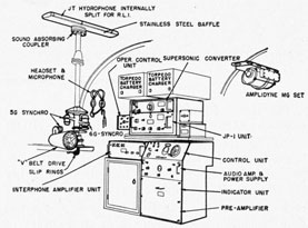
Figure 13-4 shows the JT system. In this
figure the supersonic converter, which permits the
JP amplifier to be used with ultrasonic sounds,
is mounted above the JP-1 amplifier.
The JT equipment uses a 5-foot line hydrophone. Because the JT hydrophone is longer than
the JP, the JT has greater directivity. The bearing of the JT hydrophone is relayed by synchros
to the control unit. The RLI is also on the control unit. The torpedo battery chargers shown in
figure 13-4 are not a part of the JT equipment.
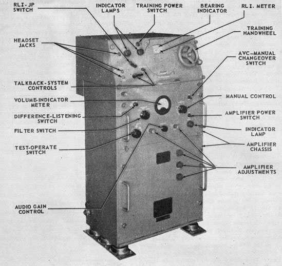
The master control unit (figure 13-5), shown
below the JP-1 unit (figure 13-4), contains pre-amplifier, amplifier, and RM circuits. The bearing indicator is merely a bearing card attached to
a 5F synchro receiver. The RLI is a pointer below
the bearing indicator.
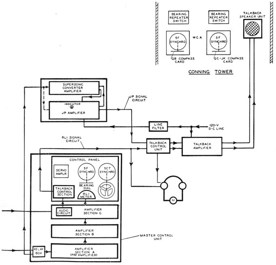
Block Diagram
A block diagram of the JT equipment, including
the signal circuits, is shown in figure 13-6. The
signal from the hydrophone can be connected
either to the master control unit, or to the JP circuits shown above the control unit. The master
control unit contains RLI circuits for taking accurate bearings on sonic sounds. The JP amplifier can be used with or without the supersonic
converter.
Figure 13-4 -JT listening system.
243
Figure 13-5 -Master control unit of the JT equipment.
The right-left indicator operates on the same
principles as the bearing-deviation indicator (BDI)
-that is, the two signals from the halves of the
hydrophone are added, subtracted, shifted in
phase, and then compared to indicate whether
the hydrophone is trained to the right or left of the
on-target position. The RLI makes it possible to
take bearings on sonic sources to an accuracy of
± 1°.
The supersonic converter is used with only the
JP amplifier for receiving ultrasonic noises up to
65,000 cps. The hydrophone signal is switched
manually to the converter, which has oscillators and
filters. The oscillators heterodyne the ultrasonic
signals to sonic frequencies. The signals are then
amplified in a part of the JP amplifier and are
applied to the tuning-eye indicator for taking
bearings on the source of the ultrasonic sound.
244
The JP amplifier can be used to receive either
the output of the supersonic converter or the hydrophone output directly. It is seldom used in
the latter way because when so operated it indicates the bearing of sonic sounds, and the RLI
circuits in the master control unit indicate the
bearing of sonic sounds with greater accuracy.
Therefore, the RLI is used generally for sonic
listening, and the supersonic converter and JP
are used for ultrasonic listening. Although the
RLI circuit has inherently greater bearing accuracy than the tuning-eye circuit of the JP, the
latter has as good accuracy for ultrasonic listening
as the RLI has for sonic listening because the hydrophone is more highly directional for signals of
high frequency.
Training
The hydrophone is trained by a servo system
operated from the master control unit. The hand-wheel on the master control unit is connected to
the 5CT synchro, which controls the servo amplifier. The servo amplifier controls the amplidyne-type motor-dynamo amplifier, which operates the
training motor. The bearing of the hydrophone
is transmitted by synchro transmitter 5G to the
synchro receivers in the conning tower and the
master control unit.
A field-change kit has been supplied for the JT
equipment. The kit adds maintenance of true
bearing (MTB) and generated target tracking (GTT)
to the training system. The MTB units compensate automatically for changes in the course of the
submarine so that target tracking with MTB is
smoother than unaided handwheel tracking. The
GTT units provide the operator with aided tracking
of a target designated at the fire control
station. In GTT operation, computed target
bearing from the fire control computer is checked
against observed bearing to aid in tracking the
target.
Hydrophone
The hydrophone consists of 10 nickel cylinders
placed collinearly. Each cylinder is surrounded
by a coil, in which an impulse is developed magnetostrictively each time the tube is compressed or
expanded by a pressure wave.
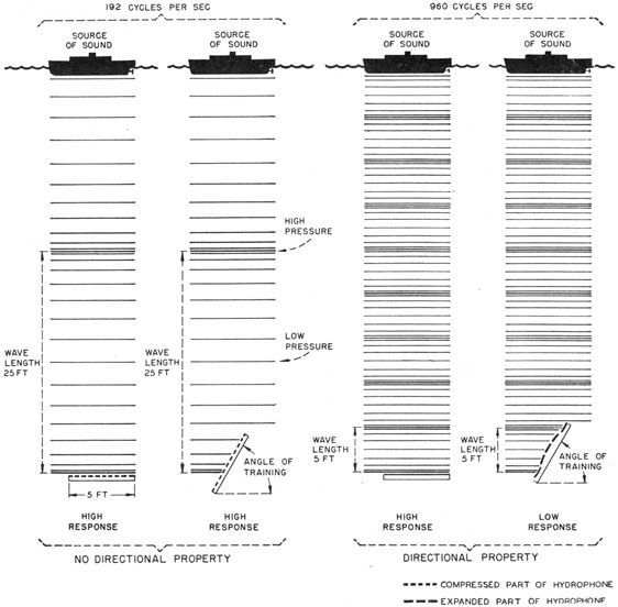
The directional characteristics of the hydrophone depend on the ratio of the wavelength of the
incident sound to the length of the hydrophone, as
shown in figure 13-7. At sound frequencies below
960 cps, the wavelength is longer than the 5-foot
length of the hydrophone. When such a sound
strikes the hydrophone, all the nickel tubes are
subjected to equal pressure regardless of the
orientation of the hydrophone, as shown in figure
13-7. However, when sounds of short wavelength strike the hydrophone, some tubes are
compressed and others are expanded, depending
on the orientation of the hydrophone. The coils
are connected in series. Maximum response is
obtained when the hydrophone is broadside to the
incident wave, because in this case all of the
voltages are series-aiding.
A steel and rubber baffle is mounted on the rear
of the hydrophone to absorb sound coming from
the rear. This baffle reduces the response of the
hydrophone to sounds from the rear and prevents
ambiguity in bearing measurement.
RLI OPERATION
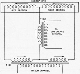
Sum and Difference Inputs
The hydrophone is split into two halves. When
the RLI-JP switch on the master control unit is
switched to the RLI position, the hydrophone
halves are connected as shown in figure 13-8.
The impulses in each coil of the hydrophone add
vectorially. If the currents in the coils are like
those shown in figure 13-8, the output of T101
obviously depends on the sum of the currents in
the two halves of the hydrophone, whereas the
output of T102 depends on the difference in the
currents in the two halves.
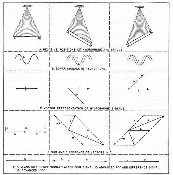
Three relative positions of the hydrophone and
target are shown in figure 13-9, A. When the
hydrophone is oriented so that the wavefront
strikes it at an angle, signals will be established in
both the sum and difference channels. These will
be exactly 90° out of phase.
Figure 13-9, B, shows the hydrophone signals
for the three orientations shown in figure 13-9, A.
Figure 13-9, C, is the vector representation of the
signals shown in figure 13-9, B. Figure 13-9, D,
shows the vector sum and difference of the signals.
Note that the sum and difference signals at the
input to the RLI circuit are always 90° out of
phase. Note also that on one side of the true bearing the difference leads the sum, and that on the
245
other side of the true bearing the sum leads the
difference. In the RLI circuit the difference signal
is advanced by 90° with respect to the sum so that
it is either in phase or 180° out of phase with the
sum signal, as shown in figure 13-9, E. The difference signal is advanced 90° with respect to the
sum, by advancing it 135° and by advancing the
sum signal 45°, as shown in figure 13-10. The
same effect could have been obtained by advancing
only the difference signal 90°.
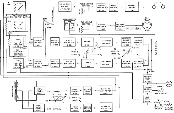
Amplifier Circuit
Figure 13-10, shows that the sum and difference
signals from the hydrophone are amplified in two
preamplifier stages and then passed through a
filter that removes all frequencies below 500 cps
and above 14,000 cps. The signals then pass
through the test-operate switch. This switch is
a six-position switch, three positions of which provide different amounts of attenuation of the signals.
Figure 13-6. -Block diagram of the JT system.
246
The other three positions provide means for adjusting certain critical components.
After leaving the test-operate switch, the sum
and difference signals are amplified further in two
stages and then pass through a filter that attenuates all signals below 5 kc and above 9 kc. The
signals then pass through the phase-shifting networks. The sum signal is advanced 45° in phase
in its network, and the difference signal is advanced 135° in phase in its network. This phase
shift makes the sum and difference signals either
in phase or 180° out of phase, as explained
previously.
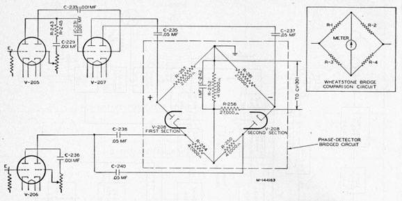
After leaving the phase shifters, the sum and
difference signals are applied to the first phase
detector. Figure 13-11 shows the first phase-detector circuit and a Wheatstone bridge for comparison. This detector consists of a bridge circuit
in which two of the arms contain series aiding
diodes (the two sections of V208). The sum
Figure 13-6 -Block diagram of the JT system-Continued.
247
Figure 13-7 -Hydrophone response to sound waves of different wavelengths.
signal push-pull output from V207 is applied across
opposite corners of the bridge and tends to make
both diodes conduct simultaneously during one
half of each cycle. The difference signal output
from V206 is applied across R254 and R250 as a
bias. The bias is applied simultaneously to the
cathode of the first section of V208 and the plate
of the second section thus biasing the two diodes
with opposite polarity. Thus, one or the other
of the diodes can conduct depending upon whether
the difference signal is in phase or 180° out of
phase with the sum signal. The output of the
bridge is the d-c signal across R252. The polarity
of this signal depends upon which diode conducts.
The a-c component is bypassed to ground by
capacitor C242 in shunt with the output.
The output of the bridge cannot be amplified
and applied directly to the RLI meter because the
amplitude distortion produced in the amplifier
stages causes an erroneous indication of the meter.
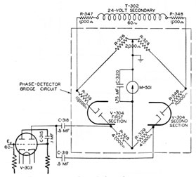
Therefore, the output of the bridge is interrupted
by a 60-cps synchronous vibrator, CV-301,
248
amplified, and then is detected in the second phase detector, shown in figure 13-12. The second phase
detector consists of a bridge circuit in which two
of the arms contain series aiding diodes (the two
sections of V304). A 60-cps reference voltage
from transformer T302 is applied across opposite
corners of the bridge and tends to make both
diodes conduct simultaneously during one half of
each cycle.
The output of the vibrator is a 60-cps square
wave voltage which is amplified in V303 and appears across R328 and R329 of the bridge circuit
as a bias. The output of V303 is applied simultaneously to the plate of the first section of twin
diode V304 and the cathode of the second section
hence biases the two diodes with opposite polarity.
Thus, one or the other of the diodes can conduct
depending upon whether the square wave signal
is in phase or 180° out of phase with the reference
voltage from transformer T302. The output of
the bridge is a d-c signal across the RLI meter
M501. The polarity of this signal depends on
which diode conducts and determines in which
direction the RLI meter will deflect.
The sum signal normally is connected to the
audio amplifier for listening. However, the difference signal for listening can be selected by depressing switch 5301 (figure 13-10)-called the
press for difference listening switch. The difference
signal is selected when the operator has a large
signal and desires to reduce the volume to
"sharpen" his pattern. Reducing signal amplitude effectively sharpens the pattern because a
small change in a small signal can be heard much
more easily than the same change in a large signal.
Figure 13-13 shows the schematic diagram of
the amplifier of the master control unit, with the
RLI circuits and audio amplifier.
ULTRASONIC LISTENING
For listening to sounds of ultrasonic frequency,
switch the hydrophone signal to the supersonic
converter, as shown in figures 13-4 and 13-6.
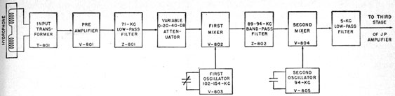
Figure 13-14 shows the block diagram of the supersonic converter, and figure 13-15 shows the schematic diagram of the converter.
The converter employs two mixers and two
local oscillators. The first mixer raises the frequency and the second lowers it. The second
oscillator is fixed at 94 kc and its associated mixer
Figure 13-8 -Hydrophone connection for RLI operation.
is preceded by a filter that passes signals in a band
of from 89 to 94 kc. Thus, the output is between
0 and 5 kc. Note that the output signal is zero
frequency when the output of the first mixer is
94 kc.
The first heterodyning oscillator is adjustable
within the frequency range of from 102 to 154 kc.
The frequencies within this range can heterodyne
with any signal of from 8 to 60 kc to produce an
output difference frequency of 94 kc from the first
mixer-corresponding to zero frequency audio output from the second mixer. Consequently, the
first oscillator is calibrated in frequency within the
range from 8 to 60 kc. The operator can measure
the frequency of any incoming sound within this
range by moving the calibrated dial until the beat
frequency of audio output is zero. The frequency
of the input signal is then indicated directly on the
dial.
Because only signals between 8 and 60 kc are
desired, the converter has a low-pass filter, actually
a low bandpass filter, that attenuates all signals
above 71 kc. In the first mixer all signals from 8
to 60 kc are heterodyned with the adjustable first
oscillator frequency of 102 to 154 kc to produce an
output difference frequency of 94 kc. The output
of the first mixer is then heterodyned with the output of the 94-kc second oscillator to produce the
audio-frequency signal. The output of the converter is connected to the third stage of the JP amplifier.
249
Figure 13-9 -Phase relations of signals in the sum and difference channels of the RLI circuit for various orientations of the hydrophone.
Triangulation-Listening-Ranging Equipment
GENERAL
In the first part of this chapter, methods of obtaining bearings with listening equipments have
been discussed. Because the great advantage of
a submarine over a surface ship lies in the fact that
it can remain undetected until very late in the
attack, or in some cases until after the completion
of the attack, the use of listening equipment for
determination of target bearings is of great importance to the submarine skipper. Targets can
be located and accurate bearings taken at ranges
up to 20,000 yards, without betraying the position
of the attacking submarine.
In order to obtain ranges, however, the
250
Figure 13-10. -Block diagram of the JT amplifier.
251
Figure 13-11. -First phase-detector circuit.
submarine must run the risk of detection by the
enemy, and the possibility of losing a target.
Until recently there have been three methods of
ranging available to the submarine approach
officer.
The oldest method is by optical means with the
use of the range finder built as an integral part of
the periscope. This method requires a knowledge
of the target height, and is, at its best, inaccurate.
In periods of low visibility this method is useless,
and in periods of high visibility, the telltale wake
of the periscope is easily detectable by the enemy
lookouts.
The second method uses a radar whose antenna
is built into the periscope. This method is extremely accurate, can obtain ranges at long distance s, and is reliable regardless of weather conditions, but the radar pulses can be received by
enemy countermeasures equipment. The periscope must, of course, be exposed, and may be
detected by the enemy ship either by visual
methods, or by surface-search radar equipment.
The third method uses echo ranging. This
method may be suitable when attacking targets
which have no sonar equipment. However, most
modern ships have facilities for reception of
these ranging transmissions, which would immediately indicate the presence of an attacking
submarine, and allow the enemy to take evasive
action and perhaps elude his attacker.
Thus it can be seen that the submariner has no
effective means of ranging, with equipment discussed thus far, that will not reveal his presence.
Extremely accurate bearings can be obtained with
listening equipments by receiving supersonic
frequencies which result in a very narrow reception pattern for the hydrophone. By placing one
hydrophone near the bow of the submarine and
another near the stern and using the length of the
Figure 13-14. -Block diagram of the supersonic-converter unit.
submarine as a base line, the range could be determined by plane trigonometry. This arrangement would give the submarine commander a
passive means of determining target range, without the disadvantages of the previously mentioned
systems.
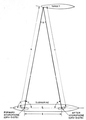
In figure 13-16 the general problem of ranging
by triangulation is presented pictorially. The
two hydrophones and the target form a triangle
as shown. Angle F is the bearing angle of the
forward hydrophone, A the bearing angle of the
after hydrophone, R the range to the target from
the forward hydrophone, c the distance from the
after hydrophone to the target, b the distance
between the forward hydrophone and the after
hydrophone, and C the supplement of F-or 180°-F. From the law of plane trigonometry, known
as the law of sines, the following relation is
obtained:
R/sin A = b/sin B = c/sin C
Angle B is equal to the difference of the forward
hydrophone bearing angle and the after hydrophone bearing angle. Thus
R/sin A = b/sin (F-A)
R = (b sin A) / sin(F-A).
Angle B is always less than 15° in this application. The sine of a small angle is approximately
equal to the magnitude of the angle in radians.
Thus
R = (b sin A) / (F-A). (13-1)
Therefore, the range to a target is equal to the
distance between the two hydrophones multiplied
239276°-53-17
by the sine of the after hydrophone bearing angle
and divided by the difference of the forward
hydrophone bearing angle and the after hydrophone bearing angle.
DESCRIPTION
The following description of the operation of an
actual triangulation-listening-ranging equipment,
refers to the model JAA equipment. This equipment is shown in figure 13-17. Actually the JAA
is an experimental model and will be replaced by
another model for quantity production. however, the basic principles and modes of operation
of the production model will probably be similar
to those of the JAA.
Two methods of computing the ranges are used
in the equipment. An electronic method, using
an electronic range recorder, computes the range
by receiving (1) a voltage proportional to the difference of the forward hydrophone bearing and
the after hydrophone bearing by means of synchros
and (2) a voltage proportional to the sine of the
after hydrophone bearing, also by means of a
synchro. The electronic range computer uses
these voltages and the distance between the two
hydrophones inserted as a constant to form a
bridge. When the bridge is balanced according to
equation (13-1), the range is the resultant, and is
recorded on a chart.
A mechanical range computer computes the
range in a like manner using gears, cams, and
servo systems.
The range information and the forward hydrophone bearing information are sent to the torpedo data computer.
Hydrophones
The hydrophones are identical to those used
with the model JT equipment and are described
253
in an earlier part of this chapter. As in the JT
equipment, the hydrophones are connected in
halves for RLI operation. In addition to these
hydrophones, two projectors called squealers are
mounted on the submarine-one forward and one
aft. They emit noises used for accurately aligning the hydrophone bearings with the baseline.
These alignments must be made when contact
with the enemy is not expected, as the noise
emitted by these squealer projectors is easily
detectable.
Control Stack
The control stack, with the mechanical range
recorder, probably will be mounted in the conning
tower. In the JAA equipment seven units, which
provide the basic functions that would be necessary in any triangulation equipment, are mounted
in the control stack. The units are (1) power
supply, (2) forward bearing-deviation indicator,
(3) after bearing-deviation indicator, (4) sonic a-f
amplifier, (5) azimuth control, (6) servo electronic
control amplifier, and (7) electronic range computer. Actually, in future equipments, some of
these units may be installed in other locations and
be operated by remote control in order to relieve
congestion in the conning tower.
The power supply unit is of conventional design
and supplies the necessary a-c and d-c voltages for
operation of the various units.
The forward and after bearing deviation indicators are identical in operation and they closely
resemble the BDI used in the JT sonar. The
triangulation-listening-ranging equipment BDI's,
however, provide a modulated a-c training control
voltage for automatic target following in addition
to BDI indication.
The sonic amplifier contains two identical channels which are used to amplify the signals for sonic
listening. The forward channel amplifies the sum
or difference signals from the forward BDI, and
the after channel from the after BDI. Also incorporated in this unit is a noise generator which
consists of a thermal oscillator followed by an
amplifier, which produces a signal to energize
either the forward or after squealer hydrophones.
The azimuth control unit contains the bearing
repeaters, remote training controls, right-left
meters, and a portion of the servo system used
-for bearing repeating and range computation.
The bearing repeaters consist of a forward repeater and an after repeater with a vernier dial
that can be used selectively with either repeater,
when the equipment is being operated manually.
When in the automatic target-following mode of
operation, this vernier dial indicates the difference between the forward and after hydrophone
bearings. The RLI meters are conventional, and
give an indication of whether the hydrophone is
trained to the right or left of the target. This
unit also supplies information to the electronic
range computer for the range computation.
The servo electronic control amplifier is a three-channel control amplifier. The forward bearing
servo channel controls the speed and direction of
rotation of the forward bearing servo motor in
accordance with the error voltages received from
the azimuth control circuits. The difference
angle servo channel is almost identical to the forward bearing servo channel. It controls the
speed and direction of rotation of the difference
angle servo motor, again utilizing the error voltage from the azimuth control unit.
Model OMA Noise-Level Monitor and Cavitation Indicator
GENERAL
Because noise is projected into the water by
various equipments on the submarine, it is desirable to measure the noise level around the submarine at frequent intervals to assure that the
noise level emanating from the submarine is not
becoming excessive. The model OMA noise-level
monitor (NLM) and cavitation indicator (CI) is
designed to measure cavitation and other noises
around own ship.
Cavitation is the formation of a vacuum around
a propeller when the speed of the propeller exceeds
a critical value. The vacuum is formed because
the propeller pushes the water away from it at a
Figure 13-16 -Target ranging by the use of two hydrophones.
rate faster than the water can flow toward it. cavitation causes loss of efficiency and a high noise
level. As cavitation is dangerous when the boat
is maneuvering to avoid an enemy, an instantaneous indication of the beginning of cavitation is
desirable.
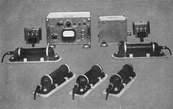
DESCRIPTION
The model OMA equipment is shown in figure
13-18. It consists of an amplifier-indicator unit,
a power supply, two neon-lamp cavitation indicators, and five hydrophones.
Four of these hydrophones are distributed along
the pressure hull to detect noises at different locations. The fifth hydrophone, which is near the
ship's screws, detects cavitation noise.
The equipment operates from a single-phase,
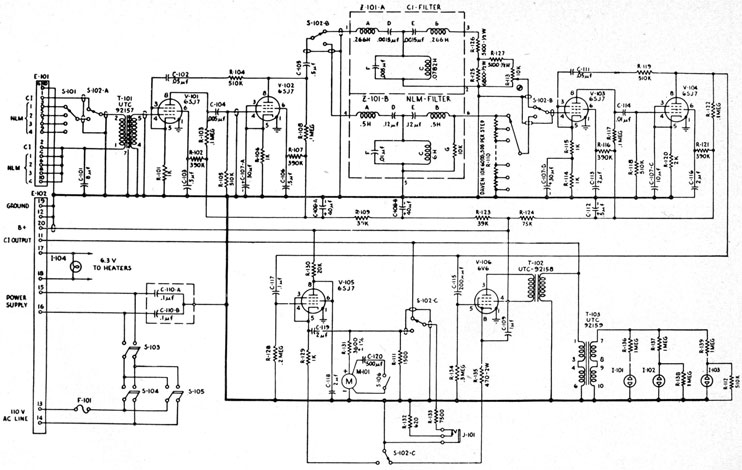
115-volt, 60-cps, a-c source. The schematic diagram of the amplifier of the OMA equipment is
shown in figure 13-19.
The four NLM hydrophones and the one CI
hydrophone are connected to the input. Switch
5101 selects one of the four hydrophones for monitoring the noise level. Switch S102nA, which selects either NLM or CI operation, is a spring-return switch and is normally set in the CI position.
The hydrophone signal is amplified in two amplifier stages and then is filtered. For CI operation,
a band-pass filter that passes a band of frequencies
of from 6 to 12 kc is used. When switch 5102 is
depressed for NLM operation, a filter that passes
frequencies of from 150 to 3,500 cps, and a 20-step
60-db attenuator are connected into the circuit in
place of the CI filter and the CI volume control,
R113. The signal from the CI volume control or
NLN attenuator is amplified in two additional
amplifier stages.
For CI operation the signal is applied to the
power amplifier, V106, for driving three neon
lamps. The neon lamps are connected so that
number 1 lamp flickers intermittently when the
voltage across the secondary of T301 is 9 volts or
more. The number 1 and number 2 lamps light
when the voltage becomes approximately 18 volts.
All three lamps light when the voltage is 25 volts or
more.
For NLM operation the signal from V104 is connected to the cathode follower, V105. The DB
meter that reads the noise level in the cathode circuit of V105, operates as a vacuum-tube voltmeter.
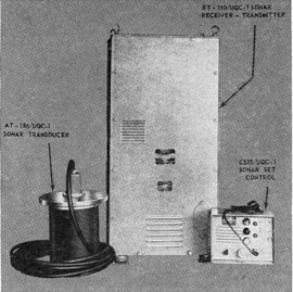
Sonar Communication Set AN/UQC-1
DESCRIPTION
The AN/UQC-1 equipment is designed for use
in submarines and surface ships to provide voice
or c-w communication through the water. As
shown in figure 13-20, the equipment consists of a
transducer, a receiver-transmitter unit, and a set-control unit.
The transducer has an omnidirectional pattern
in a horizontal plane. The transmitter applies
400 watts of single-sideband, amplitude-modulated
255
energy to the transducer. Under favorable conditions, this power permits communication at
ranges beyond 12,000 yards.
The carrier frequency is 8.0875 kc. The audio
bandwidth of the modulator is from 250 to 3,000
cps. Because only the upper sideband is transmitted, the transmitted bandwidth is from 8,338
to 11,088 cps.
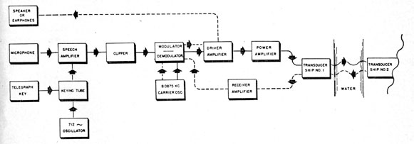
Figure 13-21 shows the block diagram of the
equipment. Solid lines in the figure indicate
transmission circuits; dotted lines indicate reception circuits. The same transducer is used for
transmission and reception.
For voice transmission the microphone output
is amplified in the speech amplifier and then
clipped to maintain a constant output level. The
modulator heterodynes the audio signal with the
8.0875-kc oscillator signal and also removes the
lower sideband and carrier frequencies. The upper
sideband is amplified in the drive amplifier, which
drives the power amplifier. The power amplifier
drives the transducer.
For c-w operation the telegraph key controls
the conduction of a keying tube, which passes a
712-cps signal from an oscillator to the speech
amplifier. This signal is also clipped to maintain a constant output level. The c-w signal is
simply a 712-cps tone on the 8.0875-kc carrier.
For reception the transducer signal is first amplified by the receiver amplifier and then heterodyned in the demodulator with the 8.0875-kc
signal. The demodulated wave contains the audio
component which is them amplified in the driver
amplifier before it is sent to the speaker or headphones.
CIRCUIT
Figure 13-22 shows the schematic diagram of
the AN/UQC-1 equipment. The relay-operated
switch, 0301, is operated from the set-control unit.
Power Supplies
The AN/UQC-1 has four rectifier-type supplies,
which are located in the power amplifier. The
first is a full-wave bridge rectifier for supplying 120-volts d-c to all the relays used in circuit switching.
The second supply is the bias supply. It consists of rectifier tube V205, filter chokes L202,
L203, and L206, and various filter capacitors and
bleeder resistors. It supplies negative bias potentials to the type-810 power amplifier tubes and to
the receiver-amplifier unit. The bias supply also
supplies voltage for operating the microphone, for
reducing hum, and for the speech amplifier.
The third supply is the plate and screen supply. It is a conventional full-wave rectifier supply.
A voltage-regulating tube, V113, regulates a part
of the output of the supply. The regulated output is used for the oscillators and clipper stages.
The fourth supply uses two type-3B28 rectifiers
to develop the high voltage for the power-amplifier
stage.
Carrier Oscillator
The 8.0875-kc carrier is obtained by dividing a
16.175-kc signal, which is generated by a crystal-controlled oscillator, V114. The 16.175-kc signal
from the oscillator is limited by clipper-rectifiers
CR103 and CR104 to aid in frequency stabilization. The clipped signal is fed to grid 1 of the
pentagrid-mixer, V115.
The band-pass filter, Z102, in the plate circuit
of the pentagrid mixer is a low-Q tank tuned to
8.088 kc. The signal at the plate of the converter
is fed to grid 3 through C120. The feedback
signal is predominantly 8 kc because the plate
tank is tuned to 8 kc and the phase-shift in the
feedback circuit cuts off the converter tube on
every second cycle of the 16-kc input. Thus, the
plate tank is shock-excited at one half the crystal-controlled frequency-that is, 8.0875 kc. The
8.0875-kc signal is amplified in V116 and sent to
the modulator.
Audio Oscillator
Tube V106 is a phase-shift audio oscillator.
The three-section feedback network between plate
and grid produces the feedback necessary to establish 712-cps oscillation that is used in the speech
amplifier when the telegraph key is depressed.
Receiver Amplifier
The receiver amplifier is a conventional two-stage RC coupled amplifier with cathode-follower
output. The gain of the amplifier is varied by
adjusting the bias on the variable-mu stages.
Figure 13-18.-Model OMA noise-level monitor and cavitation indicator.
Speech Amplifier
The speech amplifier consists of (1) an oscillator-lying network, (2) audio amplifier, and (3) limiter.
The oscillator-keying network uses tube V105.
The 712-cps signal used for c-w transmission is applied to the grid of V1O5B at all times. When the telegraph key, K401, is depressed, V105B becomes conducting and the 712-cps signal is amplified and used in the speech amplifier. When
the key is not depressed, V1O5B is cut off by the bias voltage supplied by voltage divider R131, R132, and R133 in conjunction with the reduced plate voltage caused by V1O5A which has the same plate load resistor as V105B and a positive bias. The microphone output is connected to the grid of V104A. V1O4A and V104B constitute a two-stage feedback amplifier.
The limiter consists of two type-1N34 crystal
rectifiers, which limit the modulating (voice or
c-w) signal to the modulator. A cathode follower V103B, is used to send the signal input to the modulator.
Modulator
The modulator consists of T104, T105, two filters, and rectifier assembly CR105. It is a conventional balanced modulator. The audio modulating signal (c-w or voice) is applied across T105. The filter, Z1O1A, attenuates all modulating frequencies above 3 kc. The 8.0875-kc carrier is applied between the midpoints of transformers T104 and T105. The carrier and audio signals are heterodyned in the nonlinear circuit assembly CR105, which contains four type-1N40 crystal rectifiers. Because of the center tap connections in the balanced modulator, the carrier is cancelled and does not appear in the output of T104. Only sum and difference frequencies reach the secondary of T104. The band-pass filter,
257
Figure 13-19. -Schematic diagram of the OMA amplifier.
Z101B, passes only the upper-sideband (sum)
frequencies and attenuates the lower-sideband
(difference) frequencies.
Driver Amplifier
The driver amplifier uses conventional push-pull
output with negative feedback. It consists of
amplifier V107, phase-inverter V108, push-pull
driver stages V109 and V110, and push-pull output
stages V111 and V112. The output is used to
drive (1) the power amplifier when transmitting
and (2) the loudspeaker when receiving.
Power Amplifier
The power amplifier comprises a pair of type-810
triodes in push-pull. When supplied with a 2,000-volt B+ supply, these tubes can deliver 400 watts
of power to the transducer. The output transformer, T202, is provided with two taps to match
the tubes to the load. The matching is done by
connecting the transducer to the tap that results
in maximum voltage across the output of T202.
Figure 13-20. -Sonar set AN/UQC-1.
Figure 13-21. -Block diagram of the AN/UQC-1 equipment.