12A1. The increasing use of hydraulic power
in the modern submarine. In the development
of the submarine from pre-war classes, many
changes and improvements have occurred.
One of the outstanding differences is the large
variety of submarine devices that are now
operated by hydraulic power. In early classes,
there was no hydraulic system, power requirements
were met by means of air or electricity.
Along with the steady improvement in submarine design has gone a constant extension
and diversification of the use of hydraulic
power.
12A2. Other sources of power available on
submarines. What is the reason for this
noticeable trend toward hydraulics? Obviously, hydraulic actuation is not the only
means of transmitting power throughout the
submarine. The tasks now being done by the
hydraulic system were originally performed
by hand, electricity, or compressed air.
a. Hand power. Some equipment on a
submarine is still operated exclusively by
hand, but this practice is rapidly disappearing. This is because the power requirements
exceed that which manual effort can provide
for long periods of time, and because power
operation is faster and can be remotely controlled, greatly reducing the necessary communication between crew members.
b. Electric Power Since the electrical
plant is such an important part of the submarine power system and must be used for
propulsion in any event, it would be reasonable to expect that electricity would also be
used to operate all of the auxiliary equipment
as well.
Electricity is ideally adapted for submarine equipment having few or no moving
parts; that is, lamps, radios, cooking facilities, and similar devices. But, it is not so
ideal when it is necessary to move heavy
apparatus such as the rudder and bow and
stern planes, because heavy bulky electrical
units are required. Also, when instantaneous
stopping of the driving mechanism is demanded, electric motors have a tendency to
overtravel, or drift, making fine control difficult to achieve. A further disadvantage in
the operation of electrical units is the noise
made in starting and stopping by relays and
magnetic brakes, and by shafting and other
mechanical power transmission units.
c. Pneumatic power. Since compressed
air must also be used aboard a submarine for
certain functions, this system, comprising the
compressors, high-pressure air flasks, and
air lines, offers another source of auxiliary
power. However, pneumatic or compressed
air power also has definite shortcomings.
Pressure drop caused by leakage, and the
mere fact that air is a compressible substance, may result in sponginess or lag in
operation. The high pressure necessary for
compressed air storage increases the hazard
of ruptured lines, with consequent danger to
personnel and equipment. Another disadvantage of air systems is that the air compressors require greater maintenance than
others and are relatively inefficient.
d. Comparative advantages of hydraulic
power. Hydraulic systems possess numerous
advantages over other systems of power
operation. They are light in weight and are
simple and extremely reliable, requiring a
minimum of attention and maintenance. Hydraulic controls are sensitive and afford
precise controllability. Because of the low
inertia of moving parts, they start and stop
in complete obedience to the desires of the
operator, and their operation is positive.
Hydraulic systems are self-lubricated; consequently, there is little wear or corrosion.
Their operation is not likely to be interrupted
by salt spray or water. Finally, hydraulic
units are relatively quiet in operation, an
important consideration when detection by
the enemy must be avoided.
Therefore, in spite of the presence of the
two power sources just described, hydraulics
makes its appearance on the submarine
132
because its operational advantages, when
weighed against the disadvantages listed for
electricity and air, fully justify the addition
of this third source of power in the submarine.
12A3. Hydraulic fluids. Almost any free flowing liquid is suitable as a hydraulic fluid,
if it does not chemically injure the hydraulic
equipment. For example, an acid, though
free flowing would obviously be unsuitable
because of corrosion to the metallic parts of
the system.
Water as a possible hydraulic fluid, except for its universal availability, suffers
from a number of serious disadvantages. One
is that it freezes at a relatively high temperature, and in freezing expands with tremendous force, destroying pipes and other equipment. Also, it rusts steel parts and is rather
heavy, creating a considerable amount of
inertia in a system of any size.
The hydraulic fluid used in submarine
hydraulic systems is a light, fast-flowing
lubricating oil, which does not freeze or lose
its fluidity to any marked degree even at
low temperatures, and which possesses the
additional advantage of lubricating the internal moving parts of the hydraulic units
through which it circulates.
12A4. Basic units of a hydraulic system. A
simple, hydraulic system will necessarily include the following basic equipment, which,
in one form or another, will be found in
every hydraulic system.
1.
A reservoir or supply tank containing oil which it supplies to the system as needed, and into which the oil from the return line flows.
2.
A pump which supplies the necessary working pressure.
3.
A hydraulic cylinder or actuating cylinder which translates the hydraulic power developed in the pump into mechanical energy.
4.
A Control valve by means of which the pressure in the actuating cylinder may be maintained or released as desired.
5.
A check valve placed in the line to allow fluid motion in only one direction.
6.
Hydraulic lines, that is, piping to connect the units to each other.
While the functions performed by these
six units are typical of every hydraulic system, the units are not always identified by
similar names, but rather by names descriptive of the specific operation they perform.
The submarine hydraulic system is really four
distinct systems: the main hydraulic system,
the bow plane tilting system, the stern plane
tilting system, and the steering system.
The main hydraulic system performs the
bulk of the hydraulic tasks aboard a submarine. Lines from the central power source
radiate through the ship to convey fluid under
pressure for the operation of a large variety
of services. The vent valves of the main ballast, fuel oil ballast, bow buoyancy and safety
tanks, and the flood valves of the negative
and safety tanks are hydraulically opened
and shut by power from the main system.
It also operates the engine induction and
ship's supply outboard valve, the outer doors
of the torpedo tubes, the bow plane rigging
gear the windlass and forward capstan, the
raising and lowering of the echo ranging and
detecting apparatus (sound heads), and the
main engine exhaust valves on earlier classes
of submarines. In the latest installations, the
main engine exhaust valves are operated by
pneumatic-hydraulic or air-cushion units. In
an emergency, the main hydraulic system is
also used to supply power for the steering
system and for the tilting of the bow and
stern diving planes, although these systems
normally have their own independent power
supply units.
On the latest classes, the periscopes and
antenna masts are also hydraulically operated
as units of the main hydraulic system. (In
earlier classes, they are electrically operated.)
To perform these numerous tasks, a
variety of valves, actuating cylinders, tanks,
and manifolds are required, as well as the
pumps for building up the required power.
The units in the main hydraulic system fall
conveniently into five groups:
133
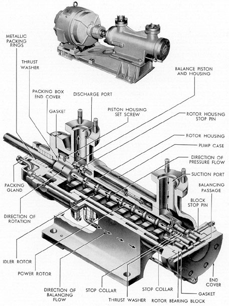
Figure 12-1. IMO pump.
134
1.
Power generating system.
2.
Floods and vents.
3.
Periscope and radio mast hoists.
4.
Forward and after service lines.
5.
Emergency systems.
FigureA-19 shows a schematic view of
the main hydraulic system in the submarine.
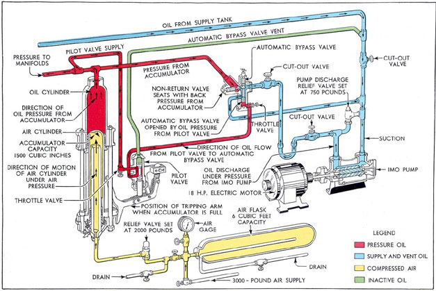
B. POWER GENERATING SYSTEM
12B1. General arrangement. The power generating system comprises a group of units,
the coordinated action of which provides the
hydraulic power necessary for the operation
of the main hydraulic system. It consists of
the following principal parts:
a. The IMO pumps, located in the pump
room, which supply hydraulic power to the
system.
b. The main supply tank, located in the
control room, which contains the oil needed
to keep the system filled.
c. The accumulator, located in the pump
room, which accumulates the oil from the
pump and creates pressure oil which is maintained at a static head for instant use anywhere in the system.
d. The main hydraulic manifolds, located in the control room, which act as distribution and receiving points far the oil
used throughout the system.
e. The pilot valve, a two-port, fitted lap-fitted trunk, cam-operated slide valve, located in the pump room, which directs the
flow of oil that causes the automatic bypass
valve to open or shut.
f. The automatic bypass and nonreturn
valves which are located in the pump room.
The automatic bypass valve directs the flow
of pressure oil in obedience to the action of
the pilot valve. The nonreturn valve prevents
the oil from escaping through the open automatic bypass.
g. Cutout valves, serving various purposes throughout the system and nonreturn
valves which allow one-way flow.
h. The back-pressure tank, or volume
tank, located in the control room and containing compressed air at a pressure of 10 to
25 psi, provides the air pressure on top of
the oil in the main supply tank which keeps
the entire system full of oil.
i. The accumulator air flask, located in
the pump room, which serves as a volume
tank for the accumulator, allowing the air
to pass to and from it when the accumulator
is loading or unloading.
12B2. IMO pump. Hydraulic systems need,
in practice, some device to deliver, over a
period of time, and as long as required, a
definite volume of fluid at the required pressure.
The IMO pump (Figure 12-1) is a power-driven rotary pump, consisting essentially of
a cylindrical casing, horizontally mounted,
and containing three threaded rotors which
rotate inside a close-fitting sleeve, drawing
oil in at one end of the sleeve and driving it
out at the other end.
The rotors of the IMO pump, which resemble worm gears, are shown in Figure 12-1.
The inside diameters of the spiral threaded
portions of the rotors are known as the troughs
of the thread; the outside diameters or crests
are known as the lands. The troughs and
lands of adjacent rotors are so closely intermeshed that as they rotate, the meshing surfaces push the oil ahead of them through the
sleeve, forming, in effect, a continuous seal
so that only a negligible fraction of the oil
that is trapped between the lands can leak
back in the direction opposite to the flow.
The center rotor is power driven; its
shaft is directly coupled to a 15-hp electric
motor which drives it at 1750 rpm. The other
two rotors, known as idlers, are driven by the
center rotor which, through the intermeshing
of its threads with the idlers, communicates
the shaft power to the idlers and forces them
to rotate in a direction opposite to the center
rotor. The rotation of the center rotor is
clockwise as viewed from the motor end of
the coupling shaft, while the two idler rotors
rotate counterclockwise.
135
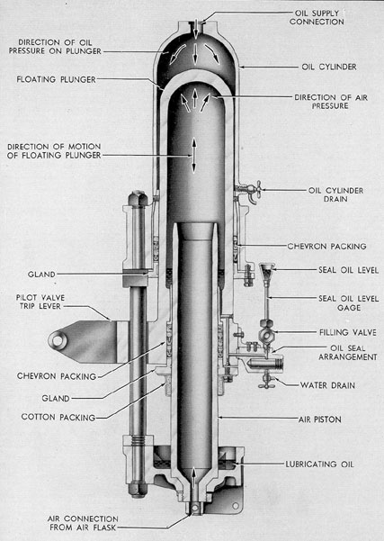
Figure 12-2 Hydraulic accumulator.
136
The end of the power rotor nearest the
motor rotates in the guide bushing; the rotor
shaft extends out through the end plate,
where it couples to the shaft of the electric
motor which drives it. Leakage around the
shaft is prevented by five rings of 3/8-inch
square flexible metallic packing which is held
in place by a packing gland. Oil which leaks
through the packing gland falls into the drip
cup.
12B3. The main supply tank. Fluid is supplied to the pumps from the main supply
tank. (See FigureA-9). The shape of this
tank varies in different installations. Its total
capacity is 50 gallons, but the normal supply
maintained is only 30 gallons; the 20-gallon
difference is an allowance made for discharge
from the accumulator and thermal expansion
of the oil.
When the system is operating, the fluid
circulates through the power system, returning to the supply tank. However, the fluid
will not remain in the supply tank for any
length of time, but will be strained and again
pumped under pressure to the accumulator
and the manifolds.
Glass tube sight gages mounted on the
side of the reservoir, or supply tank, give
minimum and maximum readings of the
amount of oil in the tank. A drain line and
valve near the bottom of the tank provide a
means for draining water that may have
accumulated there.
The back-pressure tank is connected by
a length of pipe to the top of the supply tank
(air inlet). It maintains an air pressure of
10 to 25 psi on the oil in the supply tank.
This forms an air cushion between the top
of the tank and the body of the fluid and
maintains the system in a filled condition.
An air relief valve set to lift at 40 pounds
prevents the building up of excessive air pressures in the supply tank.
12B4. Accumulator. The 1,500-cubic inch air-loaded hydraulic accumulator is located in
the pump room. (See FigureA-19.) Figure
12-2 shows a schematic view of the accumulator.
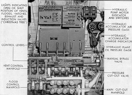
Figure 12-3. Main hydraulic control station.
137
The accumulator is essentially a hollow
plunger free to move vertically within a
stationary oil cylinder and over a stationary
hollow air piston. The oil cylinder is connected to the pressure side of the manifold
and the hollow air piston is connected to an
air flask. The air flask is located in the pump
room on the port side. The flask is charged
through the accumulator air-loading manifold
(located in the control room) from the high-pressure air system to a maximum of 1,950
psi to give a maximum oil pressure of 750 psi.
The top of the movable plunger is therefore
subjecting oil in the cylinder to a pressure
caused by the air pressure with in the plunger.
An indicator showing the position of the
accumulator plunger is installed in the control room adjacent to the main manifold.
The accumulator performs the following
functions:
a.
It controls oil delivery to the hydraulic system from the hydraulic pump.
b.
It maintains a constant pressure on the hydraulic system.
c.
It provides a reserve supply of oil under pressure to permit the operation of gear when the pump is shut down and to supplement the supply of oil from the pump when several hydraulic gears are operated
simultaneously.
d.
It reduces shock to the system when control valves are operated.
12B5. Main hydraulic control station. Normal operation of the various hydraulically
operated units of the vessel is controlled
from the main hydraulic control station is
the forward port corner of the control room.
(See Figure 12-3.)
Here, in one group, are located:
1.
The main cutout manifold.
2.
The vent control manifold.
3.
The flood control and engine air induction manifold.
4.
The IMO pump stop and start push buttons.
5.
The main plant oil pressure gage.
6.
The hydraulic accumulator air pressure gage.
7.
The manual bypass valve.
8.
The pressure cutout valve,
9.
The hydraulic accumulator charge indicator.
10.
The Christmas Tree.
Thus, all units necessary to control the
main hydraulic system are grouped in one
place for efficiency and facility of operation.
12B6. Main cutout manifold. The main cutout manifold consists of eight valves, four of
which are return valves on the upper row of
the manifold, and four of which are supply
valves on the lower part of the manifold.
The Supply valves from forward to aft,
control the following:
a.
Hydraulic service forward.
b.
Emergency steering.
c.
Emergency bow and stern plane tilting and normal bow plane rigging.
d.
Hydraulic service aft.
The return valves from forward to aft,
control the following:
a.
Hydraulic service forward.
b.
Emergency steering.
c.
Emergency bow and stern plane tilting and normal bow plane rigging.
d.
Hydraulic service aft.
12B7. Pilot valve. The pilot valve is used in
the main hydraulic system to operate the
automatic bypass valve by directing oil under
pressure to the automatic bypass valve piston
when the accumulator is fully charged, thereby opening the bypass, and then venting off
this oil when the accumulator is discharged,
allowing the bypass to shut again. It is
mounted on or near the accumulator in such
a way that the operating arm is actuated by a cam roller which is mounted on the accumulator plunger. Hydraulic fluid from the accumulator under pressure enters the valve
at the supply port. As the accumulator is
charged, the plunger moves downward, carrying with it the cam roller. As the plunger
approaches the bottom of its stroke, the cam
bears against the lower end of the pilot valve
operating arm, pulling the piston down within the cylinder. In this position, the
138
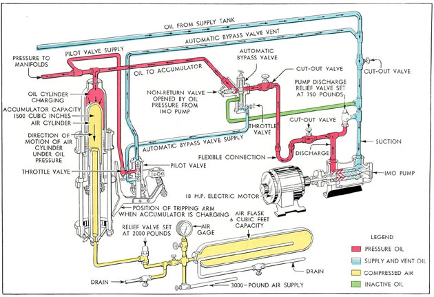
Figure 12-4, Charging the hydraulic accumulator.
139
Figure 12-5. Accumulator discharging.
140
flat-milled surface cut along the side of the piston
allows a column of oil to pass from the supply
port through the port leading to the automatic
bypass valve. (See Figure 12-4.)
This opens the automatic bypass valve,
bypassing the pressure oil from the discharge
side of the IMO pump back to the supply tank
and allowing the nonreturn valve to seat. No
more oil is delivered to the accumulator while
the pilot valve remains in this position.
12B8. Automatic bypass and nonreturn valves.
The automatic bypass and nonreturn valves
are installed between the IMO pumps and
the accumulator. There is one on each pump
pressure line. The automatic bypass valve
bypasses hydraulic oil when the accumulator
is fully charged. The nonreturn valve prevents backflow of the oil from the accumulator to the pump.
As seen in Figure 12-4, the valve body
contains two valve parts. One is the bypass
valve which is held on its seat by the valve
spring. The nonreturn valve is of the disk
type which is also seated by a spring.
During those intervals when the accumulator is being charged, hydraulic oil is delivered by the pump into the automatic bypass
and the nonreturn valve housing. The oil
pressure unseats the spring-held nonreturn
valve disk, and oil, under pressure, goes into
the line to the accumulator. When the accumulator is fully loaded, the pilot valve is
tripped and oil is directed to the automatic
bypass piston, thus forcing the automatic
bypass valve off its seat, and allowing the
oil from the pumps to return to the supply
tank. When this happens, there is not enough
pressure to keep the nonreturn valve off its
seat, so the disk valve spring returns the disk
to its seated position, thus blocking the backflow of oil from the accumulator. Oil pressure from the accumulator also assists in the
seating of the valve.
When the oil charge in the accumulator
is depleted by the use of oil to operate various
units in the system, or by leakage, the plunger
rises, causing the cam roller to bear against
the upper end of the pilot valve operating
arm, thus moving the pilot valve piston up
until the land between the two flat-milled
surfaces on the piston blocks off the supply
port from the port leading to the automatic
bypass valve. At the same time, the upper
flat surface lines up the port with the escape
port, venting the oil trapped under pressure
in the line leading to the automatic bypass
piston out through the port to a vent line,
which bleeds into the main supply tank. This
removes the pressure from underneath the
valve piston of the automatic bypass, allowing the loading spring to reseat the automatic
bypass valve and thus shut off the bypass
line.
Immediately, oil under pressure from
the IMO pump, once more directed against
the underside of the nonreturn valve, opens
this valve, allowing the oil to flow to the
accumulator.
C. OPERATIONS
12C1. Starting the main plant. Following
are the operations for starting operation of
the main plant:
a. Check the supply tank for proper oil
level.
b. Check the back-pressure for proper
pressure in the supply tank.
c. See that the hand levers on the control manifolds are in the NEUTRAL position.
d. Check the accumulator air flask pressure to see that the AIR TO ACCUMULATOR valve is open on the air-loading
manifold.
e. Check the PRESSURE CUTOUT
valve to see that it is open.
f. The manual bypass valve should be
opened before starting the motor; after the
motor has come up to speed, shut the manual bypass valve. This procedure is precautionary as the motor is not capable of
properly starting and coming up to speed
under full load.
12C2. Securing the main plant. Securing the
main plant is accomplished as follows:
a. See that the hand levers are in NEUTRAL position on the control manifolds.
141
b. Stop the motor.
c. Open the manual bypass valve allowing oil to be drained from the accumulator to
the supply tank.
12C3. Venting the system. When venting
the system, vent all lines, valves, manifolds
(except the air-loading manifold), accumulator, gages, control gears, and operating
gears. Operating lines are vented by opening
the vent valves at the operating gears. Vent
valves in the operating lines that require
venting are located abaft the diving station
on the port side of the control room.
The system should be vented if it has not
been in use for several days. The vents should
be opened only when there is pressure on the
lines.
12C4. Flood and vent control manifold. The
main vent control manifold on the submarines
built by the Electric Boat Company houses
seven control valves instead of six as on the
Portsmouth installations.
Reading from right to left, these seven
valves operate the following vent valves:
1.
Bow buoyancy tank.
2.
Safety tank.
3.
MBT Nos. 1 and 2.
4.
FBT Nos. 3 and 5.
5.
FBT No. 4.
6.
MBT No. 6.
7.
MBT No. 7.
Reading from right to left, the flood and
induction valve levers are:
1.
Engine induction and ship's supply outboard valve.
2.
Negative flood.
3.
Safety flood.
Each valve has four positions which are shown on the indicator plates next to the hand levers:
1.
SHUT, which closes the vent.
2.
OPEN, which opens the vent.
3.
HAND, which bypasses the oil allowing hand operation.
4.
EMERGENCY, which shuts off the lines to the hydraulic operating cylinder.
The lines to the hydraulic operating cylinder are shut off so that if there is a break
in the local circuit, oil will not leak out of it
from the main system, and only the local
circuit's oil will be lost.
The frame mounted on the manifold has
notches cut into it for each valve position,
into which the hand lever is firmly latched
by a lateral spring. Once placed in any position, it cannot move unless purposely moved
by the operator.
Each of these control valves operates a
flood or vent valve, at some point remote
from the manifolds, by directing a column
of pressure oil to one side or the other of a
hydraulic unit cylinder whose piston is connected, through suitable linkage, to the valve
operating mechanism. All MBT vent valves
and the safety tank and bow buoyancy vent
valves are hydraulically operated.
The operating gear consists essentially
of a hydraulic unit cylinder and suitable linkage connecting it to a vertical operating shaft
which opens and shuts the vent. Fluid under
pressure is admitted from the control valve
into the hydraulic operating cylinder. As the
piston head moves, it actuates the crank shaft.
This moves the cam, which, bearing against
the groove in the slotted link, causes it to
push up or pull down on the flat link, thereby
moving the crosshead up or down. Into the
top of the crosshead is screwed the lower end
of the operating shaft. This shaft goes up
through a packing gland in the pressure hull
to the superstructure, where the mechanism
that opens and shuts the vent is located.
12C5. The hydraulic flood valve operating
gear. The flood valves on the safety and
negative tanks are hydraulically operated.
The crossarm and hand grips are for hand
operation in case of failure of the hydraulic
power.
It is essential to understand that the
main piston rod and the tie rods are all
rigidly yoked together through the crosshead.
Impelled by the hydraulic pressure against
the piston head, all three rods move inward
or outward as one solid piece. To open the
valve, hydraulic fluid from the control valve
is admitted into one end of the cylinder
142
moving the piston head outward. The motion is
communicated through the crosshead. The
tie rods, screwed rigidly into this crosshead,
are pushed outward; the outboard connecting rods, through the crank, push the operating shaft out, opening the flood valve. Return
oil, meanwhile, flows out of the opposite end
of the cylinder back to the control valve.
To shut the valve, the flow of hydraulic
fluid is reversed, pushing the button inward.
12C6. The periscope. A pair of hydraulic
cylinders is bracketed into the periscope fairwater, at the top of the conning tower. The
piston heads and piston rods are bolted to a
yoke which carries the periscope; in other
words, the pistons and periscope are rigidly
connected together and travel as a unit. As
the pistons are raised by admitting hydraulic
pressure to the undersides of the piston heads,
the periscope extending through the center
of the fairwater slides up from its well and
is projected upward.
A distinctive feature of this type of hoist
is the fact that the control valve admits
hydraulic fluid only to the lower ends of the
cylinders. No oil is present on top of the
piston heads except that which leaks past the
piston from the pressure side. Overflow lines
and a settling tank located in the conning
tower are provided to catch any oil that may
leak up past the piston heads.
To lower the periscope, the lines from
the ports at the lower ends of the cylinders
are simply opened to the return line, and the
periscope and pistons are allowed to descend
by their own weight, forcing the oil out of
the cylinders into the return line.
12C7. The vertical antenna hoist. The vertical antenna hoist need not be discussed in
detail, as it is almost identical to the periscope hoist in arrangement, structure, and
operating principles.
In addition to the automatic trip arrangement for avoiding the hard stop at the top of
its travel, the vertical antenna hoist also has
a dash-pot arrangement and a piston head
with tapered grooved cut toward its underside, which help to bring it to an easy stop
at the bottom.
D. FORWARD AND AFTER SERVICE LINES
12D1. General arrangement. There are two
sets of hydraulic lines extending from the
main cutout manifold to both ends of the submarine. These lines, known as the foreward
and after service lines, furnish power to a
miscellaneous group of hydraulically operated
submarine equipment; specifically, these lines
service the following apparatus:
a. The after service lines supply power
for the operation of:
1.
Main engine outboard exhaust valves (hydropneumatic on latest installations).
2.
Outer doors of the four after torpedo tubes.
3.
Periscopes and vertical antenna hoists (latest installations).
b. The forward service lines supply power for the operation of:
1.
Bow plane rigging.
2.
Windlass and forward capstan.
3.
Two echo ranging and sound detection devices (raise or lower).
4.
Outer doors of the six forward torpedo tubes.
Hydraulic pressure is distributed to the
service lines at the main cutout manifold by
two valves. One line is marked Service forward, the other line is marked Service aft.
The return lines terminate in two similarly
named valves on the main cutout manifold.
12D2. Torpedo tube outer door mechanism.
The torpedo tube outer doors are hydraulically
operated as separate units from the fore and
aft service lines. There are ten torpedo tubes
in all, six forward and four aft.
The outer door-operating mechanism consists essentially of the hydraulic cylinder,
piston and power shaft, the control valve and
operating handle, and a jack screw for hand
operation. All parts are mounted on the torpedo tube itself and controlled from its breech.
143
The hydraulic cylinder contains a piston
that is moved by hydraulic power. It is connected rigidly to the power-operating shaft,
the motion of which opens or shuts the outer
door. The hydraulic power is directed to one
side or the other of the hydraulic cylinder by
the control valve. This allows flow of hydraulic power from the supply side of the
forward or after service lines and feeds it
back to the return side. The control valve
is operated by the operating handle, a push-pull arrangement which slides in and out
lengthwise through the ready-to-fire interlock tube. The operating handle is connected
to the control valve by the inner slide which
is attached to the control valve linkage by
the operating lug.
Safe operation of a torpedo tube is a
delicate and complicated process, involving a
number of different conditions which cannot
be allowed to occur simultaneously. For example, it is obvious that when the outer door
is opened to the sea, the inner door must be
locked shut and vice versa; the tube must
not be made ready-to-fire unless different
interlocks are properly engaged.
For hand operation of the outer doors,
a hand-operating shaft is provided, with a
squared end, over which an operating crank
fits. This turns the hand shaft driving gear.
This gear is meshed with the jack nut, which
in turn is threaded into the threaded portion
of the power-operating shaft. Therefore, as
the jack nut is turned, the power-operating
shaft travels through it, opening or shutting
the outer door. In order to operate this by
hand, the control valve must be in the hand
position so that the fluid trapped in the hydraulic cylinder will not act as a hydraulic
lock against the motion of the piston.
The operating handle therefore has three
positions: OPEN (handle pulled all the way
out toward the operator), in which the power
operating shaft, moved by hydraulic power,
will open the outer door; SHUT (handle
pushed in all the way away from the operator), in which the power-operating shaft
will shut the outer door; and HAND (handle
in intermediate position), in which the lines
from the hydraulic cylinder are by-passed
through the control valve.
12D3. Echo ranging and detecting apparatus.
The echo ranging and detecting apparatus is
contained in a metal sphere (called the sound
head) fixed to a cylindrical tube which is
extended downward through an opening in
the underside of the vessel in much the same
way that the periscope is extended upward
through the top. The tube is hydraulically
operated by power from the forward service
line of the main hydraulic system.
The hydraulic part of the apparatus
consists essentially of three hollow tubes, one
within the other, so arranged that the two
inside tubes act as a stationary piston fixed
to the frame of the vessel, while the outermost tube, actuated by hydraulic pressure,
acts as a movable cylinder which slides up
and dozen over it, raising or lowering the
sound head. A control valve directs the oil
pressure to one side or the other of the piston
head to raise or lower the cylinder.
A hand pump is installed in the lines for
hand operation.
E. EMERGENCY STEERING AND PLANE TILTING SYSTEMS
12E1. General. The steering and plane tilting operations are usually performed by their
own individual hydraulic systems. To insure
against failure, it is possible to use the pressure in the main hydraulic system to power
the gear that actuates the rudder and the
planes. In the main hydraulic system, this
is accomplished by connecting supply and
return lines from the other systems to the
main cutout manifold.