10A1. General description. As explained in
Chapter 5, the balance and stability of the
submarine can be upset by an unequal distribution of weights in the ship. The trim
system is employed chiefly to correct this
condition by regulating the quantity of water
in the variable tanks.
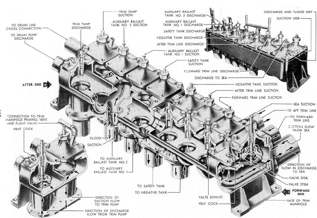
FigureA-12 illustrates the general arrangement of the trim system in the submarine. It shows the trim pump manifold,
the main flood and suction lines, the valves,
and the connections to the various trim system tanks.
The trim manifold, located on the port
side aft in the control room, is the center of
control for the entire system in that it directs
the flow of water to the various tanks. It is
a casting divided into two longitudinal compartments known as the suction and discharge sides. The discharge side of the manifold contains eight discharge control valves.
One of these valves is the trim pump discharge valve and connects the discharge side
of the manifold with the discharge side of the
trim pump. The suction side of the manifold
contains eight suction control valves, and is
connected to the suction side of the pump
through the trim pump suction valve.
The remaining seven discharge and seven
suction valves control the flood and suction
from the following lines:
1. Trim pump suction and overboard
discharge line.
2. Trim line forward flood and suction.
3. Trim line aft flood and suction.
4. Auxiliary ballast tank No. 1 flood
and suction.
5. Auxiliary ballast tank No. 2 flood
and suction.
6. Negative tank flood and suction.
7. Safety tank flood and suction.
The trim lines forward and aft serve
the two trim tanks and the two WRT tanks,
while auxiliary ballast tanks No. 1 and No. 2
are served by their own flood and suction
lines; all of these tanks make up the variable
ballast tanks group. The remaining flood and
suction lines are connected to the negative
and the safety tanks, called the special ballast
tanks.
Cross connection of the trim pump and
the drain pump is made by two flanged connections on the after end of the longitudinal
axis of the manifold. One connection is on
the discharge side, the other on the suction
side.
The trim pump, located in the after end
of the pump room, provides pumping power
for the system. It draws water into its suction side, through the suction side of the
manifold, from the tank being pumped, and
discharges it through its discharge side into
the discharge side of the manifold, which
directs the water to the tank being filled.
When it is desired to pump to one of these
tanks by means of the trim pump, the discharge valve on the trim pump manifold controlling this particular tank is opened. When
water is to be removed from a tank by means
of the trim pump, its valve on the suction side
of the manifold is opened. Thus, the trim
manifold control valves serve to put any part
of the trim system on suction or discharge.
For example, in pumping from forward trim
tank to after trim tank, the water is drawn
through lines from the forward trim tank
through the suction side of the manifold and
into the suction side of the trim pump, and
forced by pump action through the discharge
side of the trim pump, through the discharge
side of the trim manifold, and then through
lines into the after trim tank.
The trim line forward is a 3-inch line
extending from the trim manifold in the forward torpedo room. The forward trim manifold controls the flooding and pumping of the
forward trim tank and the forward WRT
tank.
The trim line aft is also a 3-inch line,
terminating in the after torpedo room at the
after trim manifold, which controls the flooding
108
and pumping of the after trim tank and
the after WRT tank.
The Nos. 1 and 2 auxiliary ballast tanks
are piped directly to their suction and discharge valves on the trim pump manifold.
The flooding or pumping of these tanks can
be accomplished only through the trim manifold. On the other hand, the flooding and
draining of the safety and the negative tanks
can be accomplished in two ways: either by
the use of their suction and discharge valves
on the trim manifold, or directly from sea
by use of their flood valves. In the latter case,
the blowing is accomplished by opening the
flood valves and admitting compressed air
into the tanks, thus forcing the water out;
while the tanks are flooded by opening both
the flood and the vent valves, allowing the
sea to enter directly into the tanks.
The trim pump suction and overboard
discharge line, connecting the trim manifold
with the sea, provides the trim system with
an overboard discharge to, or direct flooding
from, the sea. In addition to the suction and
discharge valves on the trim manifold, this
line has also a sea stop valve and a magazine
flood valve. The sea stop valve is used to shut
off the sea from the trim system and the
magazine flood valve. The magazine flood
valve guarantees, when the sea stop valve is
open, an immediate source of sea water to
the ammunition stowage and the pyrotechnic
locker.
As stated before, the main function of
the trim system is to shift and adjust the distribution of weight throughout the submarine. This is done by means of transferring
water ballast from one variable tank to another, adding water to the variable tanks or
discharging excess water from the tanks overboard. Therefore, the water handled by the
trim system is measured in pounds; and a
gage, graduated in pounds to show the amount
of water transferred by the trim pump, is
located above the trim manifold where the
operator can observe its reading.
Because the trim pump used on the latest fleet type submarine is of the centrifugal
type, it must be primed before beginning the
operation. A priming pump is used for this
purpose. It primes the trim pump by removing all air from the trim pump casing, the
trim manifold, and the lines leading to it,
thus allowing water to replace the air in this
equipment and fill it completely. It should
be noted that some submarines are equipped
with a trim pump of the reciprocating or
plunger type, similar to the drain pump shown
in Figure 10-5.
The trim system can also be used to supply or drain water from the torpedo tubes.
Water for flooding torpedo tubes is normally
taken from the WRT tanks through tube
flood and drain lines. These lines are controlled by the torpedo tube flood and drain
valves.
The trim line forward and the trim line
aft are provided with hose connections, one
in each compartment of the submarine. These
connections can be used for fire fighting, or
for bilge suctions in those compartments that
do not have bilge suction facilities. Of course,
if the connections are used for bilge suction
the trim line must be on suction, and if for
fire fighting, the line must be on discharge.
B. TRIM PUMP
10B1. Source of power. The trim pump,
Figure 10-1, located on the port side of the
pump room just forward of the after bulkhead, is driven by a 10/25 horsepower motor
directly connected by means of a flexible
coupling to the drive shaft of the trim pump.
The controller relay panel for the motor
is mounted on the after bulkhead of the pump
room. However, the motor is started or
stopped by push button controls in the control room. Once started by these controls, the
speed of the pump and, thereby, the rate at
which water is moved in the system, is regulated by a rheostat control, also located in
the control room just below the push button
switch (Figure 10-2).
109
Figure 10-1. Trim pump.
110
Figure 10-2. Trim pump controls.
While the trim pump is driven by an
electrical motor, the starting of the motor
does not guarantee that the trim pump will
pump water, for the trim pump, being of the
centrifugal type, cannot pump air. Therefore, it cannot be operated until the system
is free of air.
10B2. Priming pump. Freeing the system of
air is the purpose of the priming pump,
located outboard of the trim pump. Since any
appreciable amount of air entering the inlet
side of the trim pump will cause it to lose
suction and thereafter run without pumping,
it is necessary to know when this critical condition has been reached. To indicate the
amount of air in the trim system a vacuum
gage is provided which is mounted in the
control room. When the vacuum gage indicates less than 21 inches of vacuum, the
priming pump must be operated before the
trim pump is started. The priming pump,
like the trim pump, is started by push button
controls located in the control room. The
priming pump is a vacuum pump with a float
valve in the line, running from the priming
pump to the trim manifold and the trim pump
casing. The valve consists of a float with a
ball-ended stem. The purpose of the float is
to permit the passage of air and to prevent
the passage of water into the priming pump. As the water rises in the float valve, the upper part of the ball-ended stem is automatically forced against the valve seat, thus
preventing the sea water from entering the
priming pump.
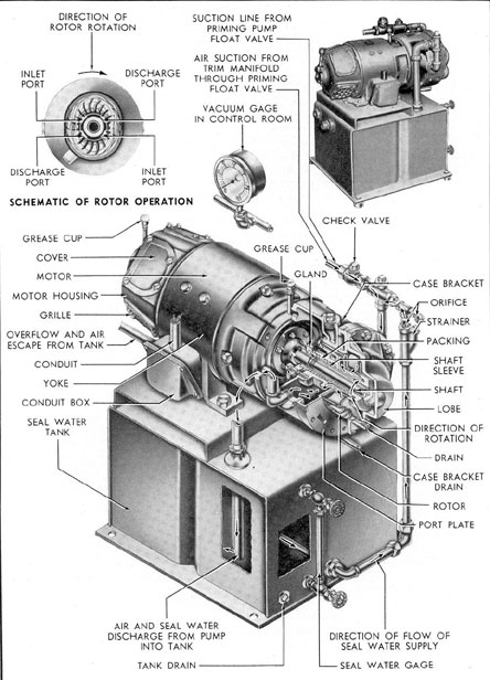
The priming pump is a self-priming
centrifugal displacement pump consisting of
three major parts: rotor, lobe, and port plate.
The rotor is made up of a series of curved
plates projecting radially from the hub. The
lobe is elliptical in shape and forms the outer
casing for the rotor. The port plate consists
of two inlet and two outlet ports corresponding to the inlet and outlet ports on the rotor.
The pump is end-mounted on the direct driving electric motor as shown in Figure 10-3.
111
Figure 10-3. Priming pump.
112
Before starting the priming pump, it is
necessary first to provide seal water to it.
This water is needed to fill the lobe partly
and provide a water seal. Water obtained
from the seal water tank should be added
until the seal water gage shows two-thirds
full. (See Figure 10-3.) Serious damage may
result if the pump is allowed to run in a dry
condition. The motor is then started by the
push button control in the control room.
In operation, the rotor revolves in the
lobe, which has been partially filled with
water, at a speed high enough to throw the
water out from the hub by centrifugal force.
This results in a solid elliptical-shaped ring
of water revolving at the same speed as the
rotor. In Figure 10-3, showing rotor operation, it may be seen that a ring of water for
a given rotor section, guided by the lobe, will
move in and out from the hub, forming a
liquid piston. As the rotor passes the inlet
port, the water ring is farthest from the hub,
and air is permitted to enter. As the rotor
advances to discharge port, the air space
becomes less and air is forced out the discharge port. This cycle is repeated twice for
each revolution of the rotor. When the
vacuum gage registers 21 inches of vacuum
in the trim system, the priming pump can be
stopped and the trim pump started.
10B3. Operation of the trim pump. A brief
review of the general principles of centrifugal
pumps will be helpful in understanding the
operation of the trim pump. As the name
implies, this type of pump employs centrifugal
force to move a liquid from a lower to a
higher level. In its simplest form, the centrifugal pump consists of an impeller rotating in a watertight casing provided with inlet
and outlet ports.
The impeller consists of two parallel disks
with curved vanes or bulkheads radiating
from the hubs and between the disks. One
of these two disks (upper or lower, depending upon where the water is brought in) has
an inlet port or circular opening called the
eye, concentric with the hub of the impeller.
Actually then, one disk holds the impeller to
the shaft while the other admits the water.
The periphery of the impeller is open, as
shown in Figure 10-1.
In operation, water enters the eye of the
impeller, is picked up by the vanes and
accelerated to a high velocity by the rotation of the impeller, and discharged by centrifugal force into the casing and out of the
discharge port. When water is forced away
from the eye of the impeller, a suction is
created and more water flows in. Consequently there is a constant flow of water
through the pump. An air bubble in the inlet
port of the pump will interrupt the action
of the pump since it will, upon entering the
impeller, break the suction at the eye which
is dependent on the presence of water. For
this reason, the pump casing and the system
served by the pump must be solidly filled with
water before pumping is commenced. This
is the function of the priming pump.
The centrifugal pump described above
has only one impeller and is known as a
single-stage pump; a pump with four impellers would be known as a four-stage pump;
with six impellers, a six-stage, and so on.
In practice however, any pump with more
than one stage is referred to as a multi-stage
pump.
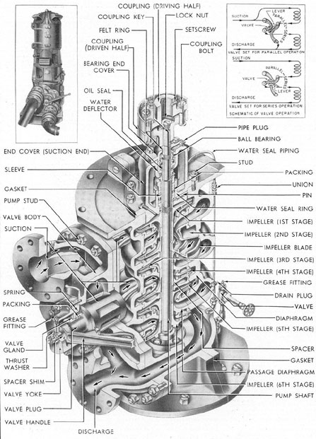
The mechanical details of the trim pump
are shown in Figure 10-1. It will be seen
that it is a six-stage centrifugal pump. The
valve shown on the forward end permits either
parallel or series operation and is manually
operated. The schematic diagram in the
upper right corner of the illustration shows
the flow of the water being pumped for both
series and parallel operation. With the manually operated series-parallel valve in the
SERIES position, the incoming water enters
the first stage, proceeds through the second
and third stages, and then back through the
series-parallel valve to the fourth, fifth, and
sixth stages. With the series-parallel valve
in the parallel position, half of the inlet water
proceeds through the first, second, and third
stages, and is then discharged through the
series-parallel valve. Simultaneously, the
other half of the inlet water is directed by
the series-parallel valve to the fourth, fifth,
113
and sixth stages and is then discharged directly. Series operation of the pump produces
twice the discharge pressure, but only one half the volume produced by parallel operation. The pump is operated in series only
when the submarine is at depths of approximately 250 feet or more and discharging to
the sea, the higher pressure being necessary
to overcome the greater sea pressure encountered at that depth.
not be started if this gage registers less than
21 inches of vacuum. If the gage shows less
than 21 inches, the system must be restored
to the proper condition by using the priming
pump. When the gage registers the required
21 inches, the priming pump is stopped and
the trim pump started.
The trim pump should not be operated
at speeds greater than are necessary to produce a rate of flow specified for a given depth.
The accompanying table lists the valve
DEPTH
PUMP OUTPUT
VALVE POSITION
On surface
1,500-2,500 pounds per minute
Parallel
0-200 ft.
1,500 pounds per minute
Parallel
200-250 ft.
1,250 pounds per minute
Parallel
400 ft. or deeper
1,000 pounds per minute
Series
250-400 ft.
1,000 pounds per minute
Series
To summarize, it must be remembered
that before starting the trim pump, it is
necessary to make certain that the trim system lines and the pump casing are free of air,
as explained earlier in this section. A vacuum
gage is provided to indicate the condition
existing in the system. The trim pump must
position and pump output in pounds of water
per minute, recommended at different depth
levels.
The pump should not be operated at a
motor speed greater than 2,400 rpm. Excess
speeds place an overload on the bearing and
mechanical parts of the pump and may cause
a breakdown.
C. MANIFOLDS
10C1. Trim manifold. In section A of this
chapter, the trim manifold is referred to as
the center of distribution for the trim system.
It acts as a switchboard between the trim
pump and the lines of the system, providing
a centralized station to direct the flow of
water to and from the variable tanks. Used
in connection with the trim manifold, but
connected to each variable tank, is a measuring gage, or liquidometer. These gages record
the amount of water in each tank, and provide the diving officer with an indication of
the amount of water ballast being redistributed by the trim manifold through the trim
system. The trim manifold is mounted hip-high of the port side of the control room just
forward of the after bulkhead, with the gage
board mounted directly above it.
Figure 10-4 shows the mechanical construction of the trim manifold, and also the
proper nomenclature of its details.
It will be seen that the manifold is a box-like, two-piece casting divided internally into
two longitudinal compartments, known respectively as the suction and discharge sides.
The suction side contains eight suction control valves, while the discharge side has eight
discharge (or flood) control valves. Each of
these 16 valves is of the dish and seat type,
with rising stems and individual bolted-on
bonnets. Name plates attached to each bonnet indicate the function of that particular valve.
114
Figure 10-4. Trim manifold.
Starting from the after end outboard of
the trim manifold, the valves in the suction
and discharge sides control the following
components:
OUTBOARD (Suction)
INBOARD (Discharge)
1. Trim pump suction
9. Trim pump discharge
2. Auxiliary ballast tank No. 2 suction
10. Auxiliary ballast tank No. 2 discharge
3. Auxiliary ballast tank No. 1 suction
11. Auxiliary ballast tank No. 1 discharge
4. Safety tank suction
12. Safety tank discharge
5. Negative tank suction
13. Negative tank discharge
6. After trim line suction
14. After trim line discharge
7. Forward trim line suction
15. Forward trim line discharge
8. Sea suction
16. Discharge to sea
The discharge valves are all on the starboard side of the manifold with the corresponding suction valves opposite them on the
port side. A special wrench is provided for
operating the valves.
Flanged outlets are cast integral with
the manifold to connect with the lines of the
system. Two outlets on the after end lead
to the drain line cross connection and to the
drain pump discharge to permit emergency
use of the drain pump to actuate the trim
system.
In all pumping operations, the trim pump
suction and the trim pump discharge valves
on the manifold must be opened to permit
flow within the system. To flood a tank, the
discharge valve for that tank must be opened
at the trim manifold; to pump a tank, its
suction valve must be opened. This should be
done before the trim pump is started. All
valves on the manifold should be shut immediately after the pumping operation is complete. Figure 10-4 shows the direction of
flow when flooding or pumping auxiliary ballast tank No. 2.
10C2. Forward and after WRT and trim tank
manifold. The WRT and trim tank manifolds
are used in conjunction with the trim manifold to control the flooding and pumping of
the WRT tanks and the trim tanks, both fore
and aft.
The forward trim manifold is located in
the forward torpedo room, portside, aft, of
the torpedo tubes. The after trim manifold
is located in the after torpedo room, portside,
The forward and the after WRT and
trim tank manifolds are identical in operation and construction, differing only in the
fact that they serve different tanks.
The body of each trim manifold is a two chambered casting containing two valves
which control flood and suction of the WRT
tank and the trim tank respectively. The
after valve in the after torpedo room and
the forward valve in the forward torpedo
room control the trim tanks. The valves are
of the disk and seat type with bolted bonnets.
The connecting passage between chambers
of the integrally cast valve casting allows
either valve to be operated independently.
The handwheels carry name plates designating the uses of the individual valves.
When open, the manifold valve marked
trim tank flood and suction permits the flooding or pumping of the trim tank from or into
the trim system when the trim line is on
service.
The other valve, marked WRT tank flood
and suction, permits the flooding or pumping
of the WRT tank from or into the trim system when the torpedo tube drain stop valve
to the WRT tank is open.
10C3. Torpedo tube drain manifold. In Section A of this chapter, the flooding and draining of the torpedo tubes were mentioned as
functions of the trim system. These functions
are controlled by the torpedo tube drain manifolds. Two of these manifolds are located in
116
the forward torpedo room, each servicing
three torpedo tubes; and two in the after
torpedo room, each servicing two torpedo
tubes.
The body of the torpedo tube drain
manifold is a three-chambered casting, housing three cam-actuated plunger type valves,
and provided with flanged outlets for connection to the trim system and to the torpedo
tube drains. The cam mechanisms are
attached to the back of the casting. Separate
control levers and connections are provided
for each of the valves.
Each, hand lever operates one cam
through the action of its connecting rod and
cam lever. In draining or flooding the tubes,
the manifold valves are used in conjunction
with the torpedo tube drain stop valve to
the WRT tank which must be open when
draining from the tubes to the WRT tank.
D. VALVES
10D1. Trim pump sea stop valve. When it
is desired to discharge water ballast from any
part of the trim system to sea, the trim pump
sea stop valve must be opened, thus providing
a passage from the trim manifold through
the pressure and outer hulls to the sea. The
same line is used to permit water to enter the
system from the sea when additional water
ballast is to be added. This valve is located
on the port side of the control room, directly
below the trim manifold. (See FigureA-12.)
10D2. Torpedo tube drain stop valve to the
WRT tank. The torpedo tube drain stop valve
to the WRT tank serves as a stop valve between the WRT tank and the individual torpedo tube drain valves.
There is a torpedo tube drain stop valve
to the WRT tank in both the forward and
the after torpedo rooms. Both of these valves
are identical in function and construction.
10D3. Magazine flood valve and testing casting. The magazine flood valve and testing
casting provide an emergency method of
flooding the magazine compartment.
The magazine flood valve is used to control this emergency flooding system. The testing casting is used to check the magazine
flood valve to make certain that it is ready
for immediate use. Both the magazine flood
valve and the testing casting are located in
the control room on the magazine flood line
of the trim system. The accessory box, containing the operating plug and wrench, is
mounted directly above the testing casting.
E. DRAIN SYSTEM
10E1. Functions. In submarines, as in all
ships, a certain amount of water accumulates
inside the hull from various sources. The
most important of these sources are:
a. Leakage at glands around propeller
shafts, Pitometer log, sound gear, periscopes,
and similar equipment.
b. Draining of air flasks, manifold
drain pans, conning tower deck gun access
trunk, and escape trunk.
c. Condensation from air-conditioning
cooling coils.
This water drains off into the bilges
and wells where a number of bilge sumps
with strainers are provided, from which the
bilge water can be pumped.
The bilge sumps and wells are pumped
periodically to prevent the excess free water
from overflowing the bilges and interfering
with the operation of the submarine. This
water is pumped out by the drain system
which consists essentially of the drain pump
and the piping connecting the pump with
the sumps and other drainage points in the
submarine. The general arrangement shown
in FigureA-12 is used in the following functional description:
The drain pump located in the pump
room provides the suction for the drain system. The pump is started and stopped by
means of an electric push button switch
located nearby in the pump room. The drain
pump has a suction and a discharge connection. A suction line equipped with a strainer
and a sight glass connects the suction side of
the pump with the main forward and after
drain lines, called the drain line forward and
the drain line aft. The drain line forward
117
and the drain line aft can be cut off by shutting their respective stop valves located in
the pump room.
Proceeding forward from the pump
room, we note that the drain line forward
extends to the forward torpedo room and
provides pumping connections for the two
bilges and the underwater log well in the
after section of the torpedo room. The drain
line terminates at the forward bilge manifold
with two valves controlling the suction from
the poppet valve drain tank and the forward
bilge.
The escape trunk drain opens into the
forward torpedo room; the water drains directly onto the deck and eventually empties
into the bilges.
There are no drain line connections in
the forward battery compartment.
The drain line aft extends to the after
torpedo room and contains pumping connections to the sumps in the compartments
in the after section of the submarine. There
are no drain line connections in the after
battery compartment. The forward engine
room has two bilge sumps connecting with
the drain line aft through two individual
lines. The after engine room also has two
bilge sumps which connect to the drain line
by means of two separate lines. In addition
to the bilge sump pumping connections, the
drain line aft also contains a suction line to
the collection tank, making it possible for
water from the collecting tank to be pumped
out through the drain system.
There is one bilge sump in the motor
room.
The drain line aft terminates in the after
bilge manifold in the after torpedo room.
Here, too, the manifold contains two valves,
controlling suction from the forward and
after bilge sumps.
Returning now to the pump room, the
drain pump suction line carries a branch connection to the pump room bilge manifold.
This manifold contains three valves controlling suction front the three pump room bilge
sumps.
The drain water from the gun access
trunk, the cable trunk, the periscopes, and
the antenna wells empties into the pump
room bilge and collects in the sumps from
which it is pumped when required.
The drain pump has three points to
which it may discharge: 1) overboard discharge, 2) compensating water main, 3) trim
system.
In addition, the drain pump is so cross
connected with the trim manifold that it can
discharge water into the trim system instead
of into its own piping. This cross connection
permits the use of either the drain pump or
the trim pump with either the trim or the
drain system, in the event that one of the
two pumps is not in operating condition.
Every branch suction line to the bilge
sumps has its own bilge stop valve. When
it is desired to pump out certain bilge sumps
or wells, the valves leading from them to the
drain line and the pump are opened; then
the required discharge valves are opened to
the overboard discharge, the compensating
water main, or the trim system, depending
upon the conditions. The drain pump is
then started and the pumping begins. After
the pumping is completed, the pump is stopped and the valves to the various lines used in
the operation are shut.
The drain system can discharge the bilge
water directly overboard, into the expansion
tank through the compensating water main,
or into the trim system through the trim
manifold.
Normally, bilge water should not be discharged directly overboard because the oil in
it will rise to the surface, indicating the
presence of the submarine. Instead, the
water should be pumped into the expansion
tank, where the water separates from the
oil before being discharged overboard.
If the trim system is used to receive the
bilge drainage, it is possible to pump this
water into the variable ballast tanks. This
should not be done normally, because discharging variable tanks to sea during trimming operations will allow bilge oil to rise
to the surface, leaving the telltale oil slick.
118
F. DRAIN PUMP
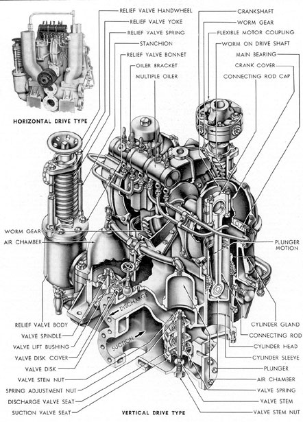
10F1. Source of power. An electric motor,
rated at 10 hp and 1,150 rpm, is used to
drive the drain pump through a worm and
worm gear assembly as shown in Figure
10-5. There are two types of pumps used:
one with vertically mounted motor as shown
in the large cutaway view of Figure 10-5, and
the other with the motor mounted horizontally as shown in the small illustration. The
cutaway view shows the mechanical construction of the pump.
10F2. Description. The drain pump is a
single-acting duplex reciprocating pump with
the cylinders mounted vertically. The two
plungers are connected to the crankshaft by
connecting rods, so that one plunger completes its downward travel at the moment the
other plunger completes its upward travel.
As a plunger moves upward in the cylinder,
it creates a vacuum (suction) which draws
water into the cylinder through the valves
from the inlet, or suction, port. When the
plunger reaches the top of its stroke and
starts its downward travel, the water forces
the suction valve down, closing the inlet port,
opening the discharge valve, and allowing
the water to flow out of the discharge port.
At the same time, the second plunger is performing the reverse operation, taking a suction, while the first plunger is discharging.
This results in a continuous flow of water
through the pump.
An air chamber is provided for each
cylinder to smooth out the flow and quiet the
pump operation by cushioning the discharge.
Air in the chamber is compressed during the
discharge. When the plunger reaches the
end of its stroke, expansion of the air tends
to keep the water flowing until the reverse
stroke begins.
A connection is provided to the 225-pound air system for recharging the chambers. Indicator lights show when the chambers need charging or venting.
10F3. Lubrication. Lubrication of the main
and the connecting rod bearings is accomplished by the multiple oiler mounted on the
pump casing. Oil is led to the bearings by
holes drilled through the crankshaft and connecting rods. The worm gear drive runs in
oil, which is cooled by sea water circulating
through a coil installed in the worm drive
housing.
10F4. Relief valve. The relief valve, set at
225 psi, is mounted on the pump body and
protects the pump from excessive pressure
in case a valve is shut on the discharge line
when the pump is operating.
A drain cock is provided to allow the
draining of all water from the pump.
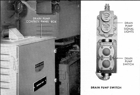
10F5. The drain pump controls. The electrical controls for the drain pump consist of
the motor switch, the air chamber pressure
indicators, and control panel. All of these
are mounted on the port side of the pump
room.
The motor switch is equipped with a
push button for starting, a push button for
stopping, and a signal light that is on when
the motor is running. (See Figure 10-6.)
G. VALVES AND FITTINGS
10G1. Drain line stop values. The drain
system is provided with two valves, known as
the forward and the after drain line stop
valves respectively. These valves will put
either drain line on service, depending on
which section of the boat is to be serviced.
The valves are located on the port side of the
pump room, forming the connection between
the line leading to the suction side of the
drain pump and the forward and after drain
lines.
The forward drain line stop valve is an
angle valve of the disk and seat type with a
bolted bonnet, a rising stem, and flanges for
connection to the lines. The after drain line
stop valve is a globe valve.
10G2. Drain pump overboard discharge
valve. When the water collected from the
bilges by the drain system is to be discharged
directly to the sea, two valves must be opened
to provide passage for the drain water.
119
Figure 10-5. Drain pump.
120
Figure 10-6. Drain pump controls.
The inboard valve is a stop check valve;
the second valve is outboard of the first and
is known as the drain pump overboard discharge valve. Both are located on the port
side forward in the pump room, and are
mounted in tandem so that the stop check
valve acts as a sea stop for the discharge
valve.
10G3. Bilge strainer. Although the purpose
of the bilges is to collect excess water, a
miscellany of solid material such as flakes of
paint and bits of metal inevitably finds its
way into the bilges. If this solid matter were
to enter the lines of the drain system, it
might clog or damage the drain pump. To
prevent this, each bilge sump is equipped
with a bilge strainer which screens the bilge
water before it enters the drain system lines
and holds back any large particles.
10G4. Macomb strainer. Although the bilge
strainers discussed in Section 10-G3 will prevent pieces of solid material larger than 1/2
inch from entering the drain system, it is
necessary to screen the water again to remove any smaller particles of debris that
might clog or damage the drain pump. Such
material is filtered out of the drain system
by the Macomb strainers.
10G5. Drain line sight glass. The drain sight
glass provides a means of visually determining the amount of oil of solid matter in the
bilge water as it flows through the lines of
the drain system. It consists of a cross-shaped
casting, two ends of which are flanged and
connected to the drain lines. The other arms
are fitted with glass plates forming a window
to allow inspection of the water in the drain
line.
10G6. Underwater log well suction line and
sump. The water that collects in the underwater log well is pumped out by the underwater log well suction line. This line extends
from the drain line and runs athwartships
along the after bulkhead of the forward torpedo room to the underwater log well.
It is equipped with a bilge strainer
which is fitted into the well. A stop check
valve is mounted in the line between the well
and the forward drain line which is opened
to pump the underwater log well.